
OMRON Power Supplies - S8FS-C
Power Supplies - S8FS-C
DOWNLOAD PDF
Model Numbers | Power Supplies - S8FS-C
Note: For details on normal stock models, contact your nearest OMRON representative.
| Power rating | Input voltage | Output voltage (VDC) | Output current | Built- in fan | Model with terminal block facing upward | Model with terminal block facing forward | Model wtih DIN rail |
|---|---|---|---|---|---|---|---|
| 15 W | 100 to 240 VAC (allowable range: 85 to 264 VAC or 120 to 370 VDC *1) |
5 V | 3 A | None | -- | S8FS-C01505J | S8FS-C01505D |
| 12 V | 1.3 A | S8FS-C01512J | S8FS-C01512D | ||||
| 15 V | 1 A | S8FS-C01515J | S8FS-C01515D | ||||
| 24 V | 0.7 A | S8FS-C01524J | S8FS-C01524D | ||||
| 25 W | 5 V | 5 A | S8FS-C02505 | S8FS-C02505J | S8FS-C02505D | ||
| 12 V | 2.1 A | S8FS-C02512 | S8FS-C02512J | S8FS-C02512D | |||
| 15 V | 1.7 A | S8FS-C02515 | S8FS-C02515J | S8FS-C02515D | |||
| 24 V | 1.1 A | S8FS-C02524 | S8FS-C02524J | S8FS-C02524D | |||
| 35 W | 5 V | 7 A | S8FS-C03505 | S8FS-C03505J | S8FS-C03505D | ||
| 12 V | 3 A | S8FS-C03512 | S8FS-C03512J | S8FS-C03512D | |||
| 15 V | 2.4 A | S8FS-C03515 | S8FS-C03515J | S8FS-C03515D | |||
| 24 V | 1.5 A | S8FS-C03524 | S8FS-C03524J | S8FS-C03524D | |||
| 50 W | 5 V | 10 A | S8FS-C05005 | S8FS-C05005J | S8FS-C05005D | ||
| 12 V | 4.2 A | S8FS-C05012 | S8FS-C05012J | S8FS-C05012D | |||
| 15 V | 3.4 A | S8FS-C05015 | S8FS-C05015J | S8FS-C05015D | |||
| 24 V | 2.2 A | S8FS-C05024 | S8FS-C05024J | S8FS-C05024D | |||
| 48 V | 1.1 A | S8FS-C05048 | S8FS-C05048J | S8FS-C05048D | |||
| 75 W | 5 V | 14 A | S8FS-C07505 | S8FS-C07505J | S8FS-C07505D | ||
| 12 V | 6.2 A | S8FS-C07512 | S8FS-C07512J | S8FS-C07512D | |||
| 15 V | 5 A | S8FS-C07515 | S8FS-C07515J | S8FS-C07515D | |||
| 24 V | 3.2 A | S8FS-C07524 | S8FS-C07524J | S8FS-C07524D | |||
| 48 V | 1.6 A | S8FS-C07548 | S8FS-C07548J | S8FS-C07548D | |||
| 100 W | 100 to 120 VAC, 200 to 240 VAC (allowable range: 85 to 132 VAC, 176 to 264 VAC, or 248 to 373 VDC (Select with the switch.) *2) |
5 V | 20 A | S8FS-C10005 | S8FS-C10005J | S8FS-C10005D | |
| 12 V | 8.5 A | S8FS-C10012 | S8FS-C10012J | S8FS-C10012D | |||
| 15 V | 7 A | S8FS-C10015 | S8FS-C10015J | S8FS-C10015D | |||
| 24 V | 4.5 A | S8FS-C10024 | S8FS-C10024J | S8FS-C10024D | |||
| 36 V | 2.8 A | S8FS-C10036 | S8FS-C10036J | S8FS-C10036D | |||
| 48 V | 2.3 A | S8FS-C10048 | S8FS-C10048J | S8FS-C10048D | |||
| 150 W | 100 to 120 VAC, 200 to 240 VAC (allowable range: 90 to 132 VAC, 180 to 264 VAC, or 254 to 373 VDC (Select with the switch.) *2) |
5 V | 26 A | S8FS-C15005 | S8FS-C15005J | S8FS-C15005D | |
| 12 V | 12.5 A | S8FS-C15012 | S8FS-C15012J | S8FS-C15012D | |||
| 15 V | 10 A | S8FS-C15015 | S8FS-C15015J | S8FS-C15015D | |||
| 24 V | 6.5 A | S8FS-C15024 | S8FS-C15024J | S8FS-C15024D | |||
| 36 V | 4.3 A | S8FS-C15036 | S8FS-C15036J | S8FS-C15036D | |||
| 48 V | 3.3 A | S8FS-C15048 | S8FS-C15048J | S8FS-C15048D | |||
| 200 W | 5 V | 40 A | S8FS-C20005 | S8FS-C20005J | S8FS-C20005D | ||
| 12 V | 17 A | S8FS-C20012 | S8FS-C20012J | S8FS-C20012D | |||
| 24 V | 8.8 A | S8FS-C20024 | S8FS-C20024J | S8FS-C20024D | |||
| 36 V | 5.9 A | S8FS-C20036 | S8FS-C20036J | S8FS-C20036D | |||
| 48 V | 4.43 A | S8FS-C20048 | S8FS-C20048J | S8FS-C20048D | |||
| 350 W | 5 V | 60 A | Yes | S8FS-C35005 | S8FS-C35005J | S8FS-C35005D | |
| 12 V | 29 A | S8FS-C35012 | S8FS-C35012J | S8FS-C35012D | |||
| 24 V | 14.6 A | S8FS-C35024 | S8FS-C35024J | S8FS-C35024D | |||
| 36 V | 9.7 A | S8FS-C35036 | S8FS-C35036J | S8FS-C35036D | |||
| 48 V | 7.32 A | S8FS-C35048 | S8FS-C35048J | S8FS-C35048D |
Note: You can use brackets that are sold separately to mount the Power Supplies to DIN Rail. Refer to Mounting Brackets (Order Separately) on Data Sheet.
*1. The range for compliance with EC Directives and safety standards (UL, EN, etc.) is 100 to 240 VAC.
*2. The range for compliance with EC Directives and safety standards (UL, EN, etc.) is 100 to 120 VAC, 200 to 240 VAC.
Mounting Brackets (Order Separately)
| Power rating | Mounting direction | Model |
|---|---|---|
| 15 W | DIN Rail | S82Y-FSC015DIN |
| 25 W | S82Y-FSC025DIN | |
| 35 W | S82Y-FSC050DIN | |
| 50 W | ||
| 75 W | S82Y-FSC150DIN | |
| 100 W | ||
| 150 W | ||
| 200 W | S82Y-FSC350DIN | |
| 350 W | ||
| 15 W | Bottom-mounting to DIN Rail | S82Y-FSC015DIN-S |
| 25 W | S82Y-FSC025DIN-S | |
| 35 W | S82Y-FSC035DIN-S | |
| 50 W | S82Y-FSC050DIN-S | |
| 75 W | S82Y-FSC100DIN-S | |
| 100 W | ||
| 150 W | S82Y-FSC150DIN-S | |
| 200 W | Bottom-mounting with L-brackets | S82Y-FSC350B (4 brackets) |
| 350 W |
DIN Rail (Order Separately)
Mounting Rail (Material: Aluminum)
| Model |
|---|
| PFP-100N |
| PFP-50N |
Mounting Rail (Material: Aluminum)
| Model |
|---|
| PFP-100N2 |
End Plate
| Model |
|---|
| PFP-M |
Note: 1. If there is a possibility that the Power Supply will be subject to vibration or shock, use a steel DIN Rail. Otherwise, metallic filings may result from aluminum abrasion.
2. If there is a possibility of the Power Supply sliding sideways, place an End Plate (PFP-M) on each end of the Power Supply.
Terminal Cover (Order Separately)
| Terminal block direction | Power rating | Applicable models | Terminal Cover model number |
|---|---|---|---|
| Models with terminal block facing upward |
25-W | S8FS-C025[][] | S82Y-FSC-C5 |
| 35-W | S8FS-C035[][] | ||
| 50-W | S8FS-C050[][] | ||
| 75-W | S8FS-C075[][] | ||
| 100-W | S8FS-C100[][] | S82Y-FSC-C7 | |
| 150-W | S8FS-C150[][] | ||
| 200-W | S8FS-C200[][] | S82Y-FSC-C9 | |
| 350-W | S8FS-C350[][] | ||
| Models with terminal block facing forward |
15-W | S8FS-C015[][]J/D | S82Y-FSC-C5MF |
| 25-W | S8FS-C025[][]J/D | S82Y-FSC-C5F | |
| 35-W | S8FS-C035[][]J/D | ||
| 50-W | S8FS-C050[][]J/D | ||
| 75-W | S8FS-C075[][]J/D | ||
| 100-W | S8FS-C100[][]J/D | S82Y-FSC-C7F | |
| 150-W | S8FS-C150[][]J/D | ||
| 200-W | S8FS-C200[][]J/D | S82Y-FSC-C9F | |
| 350-W | S8FS-C350[][]J/D |
Specifications | Power Supplies - S8FS-C
Ratings, Characteristics, and Functions
| Power rating | 15 W | |||||
|---|---|---|---|---|---|---|
| Output voltage (VDC) | 5 V | 12 V | 15 V | 24 V | ||
| Efficiency * | 115 VAC input | 80% typ. | 84% typ. | 84% typ. | 85% typ. | |
| 230 VAC input | 82% typ. | 85% typ. | 86% typ. | 87% typ. | ||
| Input | Voltage range * | Single phase 85 to 264 VAC, 120 to 370 VDC (The L terminal for the DC input is the positive side and safety standards do not apply.) (Derating is required according to the input voltage. Refer to Derating Curves on Data Sheet.) |
||||
| Frequency * | 50 /60 Hz (47 to 450 Hz) | |||||
| Current * | 115 VAC input | 0.3 A typ. | ||||
| 230 VAC input | 0.19 A typ. | |||||
| Power factor | -- | |||||
| Leakage current | 115 VAC input | 0.05 mA | 0.05 mA | 0.05 mA | 0.05 mA | |
| 230 VAC input | 0.10 mA | 0.10 mA | 0.10 mA | 0.10 mA | ||
| Inrush current * (for a cold start at 25°) | 115 VAC input | 16 A typ. | ||||
| 230 VAC input | 32 A typ. | |||||
| Output | Rated Output Current | 3 A | 1.3 A | 1 A | 0.7 A | |
| Voltage adjustment range * | -10% to 10% (with V. ADJ) | |||||
| Ripple & Noise voltage * | 100 to 240 VAC input |
30 mVp-p max. | 30 mVp-p max. | 40 mVp-p max. | 30 mVp-p max. | |
| Input variation influence * | 0.5% max. | |||||
| Load variation influence * | 1.0% max. | |||||
| Temperature variation influence | 100 to 240 VAC input |
0.03%/°C max. | ||||
| Startup time * | 115 VAC input | 490 ms typ. | 500 ms typ. | 470 ms typ. | 480 ms typ. | |
| 230 VAC input | 470 ms typ. | 480 ms typ. | 450 ms typ. | 460 ms typ. | ||
| Hold time * | 115 VAC input | 14 ms typ. | 16 ms typ. | 18 ms typ. | 15 ms typ. | |
| 230 VAC input | 83 ms typ. | 87 ms typ. | 92 ms typ. | 79 ms typ. | ||
| Addi- tional func- tions | Overload protection | Yes, automatic reset | ||||
| Overvoltage protection * | Yes, 115% or higher of rated output voltage, power shut off (shut off the input voltage and turn on the input again) |
|||||
| Overheat protection | No | |||||
| Series operation | Yes (For up to 2 Power Supplies, external diodes are required.) | |||||
| Parallel operation | No (However, backup operation is possible, external diodes are required.) | |||||
| Remote sensing | No | |||||
| Remote control | No | |||||
| Output indicator | Yes (LED: Green) | |||||
| Insula- tion | Withstand voltage | 3 kVAC for 1 min. (between all input terminals and output terminals) current cutoff 20 mA |
||||
| 2 kVAC for 1 min. (between all input terminals and PE terminals) current cutoff 20 mA |
||||||
| 1 kVAC for 1 min. (between all output terminals and PE terminals) current cutoff 20 mA |
||||||
| Insulation resistance | 100 MΩ min. (between all output terminals and all input terminals/PE terminals) at 500 VDC |
|||||
| Envi- ron- ment | Ambient operating temperature | -20 to 60°C (Derating is required according to the temperature. Refer to Derating Curves on Data Sheet.) (with no condensation or icing) |
||||
| Storage temperature | -40 to 85°C (with no condensation or icing) | |||||
| Ambient operating humidity | 20% to 90% (Storage humidity: 10% to 95%) | |||||
| Vibration resistance | 10 to 55 Hz, 0.375-mm half amplitude for 2 h each in X, Y, and Z directions 10 to 500 Hz, 0.26-mm half amplitude for 1 h each in X, Y, and Z directions |
|||||
| Shock resistance | 150 m/s2, 3 times each in ±X, ±Y, ±Z directions | |||||
| Relia- bility | MTBF | 135,000 hrs min. | ||||
| Life expectancy * | 10 years min. | |||||
| Con- struc- tion | Dimensions (W × H × D) | Refer to Dimensions. | ||||
| Weight | 150 g max. | |||||
| Cooling fan | No | |||||
| Degree of protection | -- | |||||
| Stan- dards | Harmonic current emissions | Conforms to EN 61000-3-2, GB17625.1 | ||||
| EMI | Conducted Emissions |
Conforms to EN 61204-3 Class B, EN 55011 Class B, GB9254 | ||||
| Radiated Emissions |
Conforms to EN 61204-3 Class B, EN 55011 Class B, GB9254 | |||||
| EMS | Conforms to EN 61204-3 high severity levels | |||||
| Safety Standards | Approved Standards UL: cURus UL 62368-1 (Recognition) OVC II Pol2 CSA: cURus C22.2 No62368-1 CCC: GB4943 Conformed Standards EN: EN 62368-1 OVC II Pol2 EAC (TR CU 004 / 2011, TR CU 020 / 2011) RCM (EN61000-6-4) |
|||||
| Marine Standards | No | |||||
| SEMI | No | |||||
* Refer to Conditions of below.
| Power rating | 25 W | |||||
|---|---|---|---|---|---|---|
| Output voltage (VDC) | 5 V | 12 V | 15 V | 24 V | ||
| Efficiency * | 115 VAC input | 80% typ. | 84% typ. | 85% typ. | 86% typ. | |
| 230 VAC input | 82% typ. | 86% typ. | 88% typ. | 88% typ. | ||
| Input | Voltage range * | Single phase 85 to 264 VAC, 120 to 370 VDC (The L terminal for the DC input is the positive side and safety standards do not apply.) (Derating is required according to the input voltage. Refer to Derating Curves on Data Sheet.) |
||||
| Frequency * | 50 /60 Hz (47 to 450 Hz) | |||||
| Current * | 115 VAC input | 0.49 A typ. | ||||
| 230 VAC input | 0.3 A typ. | |||||
| Power factor | -- | |||||
| Leakage current | 115 VAC input | 0.10 mA | 0.10 mA | 0.10 mA | 0.10 mA | |
| 230 VAC input | 0.20 mA | 0.20 mA | 0.20 mA | 0.20 mA | ||
| Inrush current * (for a cold start at 25°) | 115 VAC input | 16 A typ. | ||||
| 230 VAC input | 32 A typ. | |||||
| Output | Rated Output Current | 5 A | 2.1 A | 1.7 A | 1.1 A | |
| Voltage adjustment range * | -10% to 10% (with V. ADJ) | |||||
| Ripple & Noise voltage * | 100 to 240 VAC input |
20 mVp-p max. | 20 mVp-p max. | 30 mVp-p max. | 40 mVp-p max. | |
| Input variation influence * | 0.5% max. | |||||
| Load variation influence * | 1.0% max. | |||||
| Temperature variation influence | 100 to 240 VAC input |
0.03%/°C max. | ||||
| Startup time * | 115 VAC input | 390 ms typ. | 340 ms typ. | 400 ms typ. | 360 ms typ. | |
| 230 VAC input | 360 ms typ. | 350 ms typ. | 400 ms typ. | 360 ms typ. | ||
| Hold time * | 115 VAC input | 17 ms typ. | 22 ms typ. | 23 ms typ. | 21 ms typ. | |
| 230 VAC input | 103 ms typ. | 113 ms typ. | 117 ms typ. | 112 ms typ. | ||
| Addi- tional func- tions | Overload protection | Yes, automatic reset | ||||
| Overvoltage protection * | Yes, 115% or higher of rated output voltage, power shut off (shut off the input voltage and turn on the input again) |
|||||
| Overheat protection | No | |||||
| Series operation | Yes (For up to 2 Power Supplies, external diodes are required.) | |||||
| Parallel operation | No (However, backup operation is possible, external diodes are required.) | |||||
| Remote sensing | No | |||||
| Remote control | No | |||||
| Output indicator | Yes (LED: Green) | |||||
| Insula- tion | Withstand voltage | 3 kVAC for 1 min. (between all input terminals and output terminals) current cutoff 20 mA |
||||
| 2 kVAC for 1 min. (between all input terminals and PE terminals) current cutoff 20 mA |
||||||
| 1 kVAC for 1 min. (between all output terminals and PE terminals) current cutoff 20 mA |
||||||
| Insulation resistance | 100 MΩ min. (between all output terminals and all input terminals/PE terminals) at 500 VDC |
|||||
| Envi- ron- ment | Ambient operating temperature | -20 to 60°C (Derating is required according to the temperature. Refer to Derating Curves on Data Sheet.) (with no condensation or icing) |
||||
| Storage temperature | -40 to 85°C (with no condensation or icing) | |||||
| Ambient operating humidity | 20% to 90% (Storage humidity: 10% to 95%) | |||||
| Vibration resistance | 10 to 55 Hz, 0.375-mm half amplitude for 2 h each in X, Y, and Z directions 10 to 500 Hz, 0.26-mm half amplitude for 1 h each in X, Y, and Z directions |
|||||
| Shock resistance | 150 m/s2, 3 times each in ±X, ±Y, ±Z directions | |||||
| Relia- bility | MTBF | 135,000 hrs min. | ||||
| Life expectancy * | 10 years min. | |||||
| Con- struc- tion | Dimensions (W × H × D) | Refer to Dimensions. | ||||
| Weight | 250 g max. | |||||
| Cooling fan | No | |||||
| Degree of protection | -- | |||||
| Stan- dards | Harmonic current emissions | Conforms to EN 61000-3-2, GB17625.1 | ||||
| EMI | Conducted Emissions |
Conforms to EN 61204-3 Class B, EN 55011 Class B, GB9254 | ||||
| Radiated Emissions |
Conforms to EN 61204-3 Class B, EN 55011 Class B, GB9254 | |||||
| EMS | Conforms to EN 61204-3 high severity levels | |||||
| Safety Standards | Approved Standards UL: cURus UL 62368-1 (Recognition) OVC II Pol2 CSA: cURus C22.2 No62368-1 CCC: GB4943 Conformed Standards EN: EN 62368-1 OVC II Pol2 EAC (TR CU 004 / 2011, TR CU 020 / 2011) RCM (EN61000-6-4) |
|||||
| Marine Standards | No | |||||
| SEMI | No | |||||
* Refer to Conditions of below.
| Power rating | 35 W | |||||
|---|---|---|---|---|---|---|
| Output voltage (VDC) | 5 V | 12 V | 15 V | 24 V | ||
| Efficiency * | 115 VAC input | 81% typ. | 83% typ. | 84% typ. | 87% typ. | |
| 230 VAC input | 81% typ. | 84% typ. | 84% typ. | 87% typ. | ||
| Input | Voltage range * | Single phase 85 to 264 VAC, 120 to 370 VDC (The L terminal for the DC input is the positive side and safety standards do not apply.) (Derating is required according to the input voltage. Refer to Derating Curves on Data Sheet.) |
||||
| Frequency * | 50 /60 Hz (47 to 450 Hz) | |||||
| Current * | 115 VAC input | 0.66 A typ. | ||||
| 230 VAC input | 0.41 A typ. | |||||
| Power factor | -- | |||||
| Leakage current | 115 VAC input | 0.15 mA | 0.15 mA | 0.15 mA | 0.15 mA | |
| 230 VAC input | 0.30 mA | 0.25 mA | 0.25 mA | 0.25 mA | ||
| Inrush current * (for a cold start at 25°) | 115 VAC input | 16 A typ. | ||||
| 230 VAC input | 32 A typ. | |||||
| Output | Rated Output Current | 7 A | 3 A | 2.4 A | 1.5 A | |
| Voltage adjustment range * | -10% to 10% (with V. ADJ) | |||||
| Ripple & Noise voltage * | 100 to 240 VAC input |
80 mVp-p max. | 90 mVp-p max. | 90 mVp-p max. | 80 mVp-p max. | |
| Input variation influence * | 0.5% max. | |||||
| Load variation influence * | 1.0% max. | |||||
| Temperature variation influence | 100 to 240 VAC input |
0.03%/°C max. | ||||
| Startup time * | 115 VAC input | 750 ms typ. | 750 ms typ. | 760 ms typ. | 770 ms typ. | |
| 230 VAC input | 700 ms typ. | 690 ms typ. | 710 ms typ. | 720 ms typ. | ||
| Hold time * | 115 VAC input | 13 ms typ. | 14 ms typ. | 14 ms typ. | 15 ms typ. | |
| 230 VAC input | 74 ms typ. | 75 ms typ. | 75 ms typ. | 79 ms typ. | ||
| Addi- tional func- tions | Overload protection | Yes, automatic reset | ||||
| Overvoltage protection * | Yes, 115% or higher of rated output voltage, power shut off (shut off the input voltage and turn on the input again) |
|||||
| Overheat protection | No | |||||
| Series operation | Yes (For up to 2 Power Supplies, external diodes are required.) | |||||
| Parallel operation | No (However, backup operation is possible, external diodes are required.) | |||||
| Remote sensing | No | |||||
| Remote control | No | |||||
| Output indicator | Yes (LED: Green) | |||||
| Insula- tion | Withstand voltage | 3 kVAC for 1 min. (between all input terminals and output terminals) current cutoff 20 mA |
||||
| 2 kVAC for 1 min. (between all input terminals and PE terminals) current cutoff 20 mA |
||||||
| 1 kVAC for 1 min. (between all output terminals and PE terminals) current cutoff 20 mA |
||||||
| Insulation resistance | 100 MΩ min. (between all output terminals and all input terminals/PE terminals) at 500 VDC |
|||||
| Envi- ron- ment | Ambient operating temperature | -20 to 60°C (Derating is required according to the temperature. Refer to Derating Curves on Data Sheet.) (with no condensation or icing) |
||||
| Storage temperature | -40 to 85°C (with no condensation or icing) | |||||
| Ambient operating humidity | 20% to 90% (Storage humidity: 10% to 95%) | |||||
| Vibration resistance | 10 to 55 Hz, 0.375-mm half amplitude for 2 h each in X, Y, and Z directions 10 to 500 Hz, 0.26-mm half amplitude for 1 h each in X, Y, and Z directions |
|||||
| Shock resistance | 150 m/s2, 3 times each in ±X, ±Y, ±Z directions | |||||
| Relia- bility | MTBF | 135,000 hrs min. | ||||
| Life expectancy * | 10 years min. | |||||
| Con- struc- tion | Dimensions (W × H × D) | Refer to Dimensions. | ||||
| Weight | 250 g max. | |||||
| Cooling fan | No | |||||
| Degree of protection | -- | |||||
| Stan- dards | Harmonic current emissions | Conforms to EN 61000-3-2, GB17625.1 | ||||
| EMI | Conducted Emissions |
Conforms to EN 61204-3 Class B, EN 55011 Class B, GB9254 | ||||
| Radiated Emissions |
Conforms to EN 61204-3 Class B, EN 55011 Class B, GB9254 | |||||
| EMS | Conforms to EN 61204-3 high severity levels | |||||
| Safety Standards | Approved Standards UL: cURus UL 62368-1 (Recognition) OVC II Pol2 CSA: cURus C22.2 No62368-1 CCC: GB4943 Conformed Standards EN: EN 62368-1 OVC II Pol2 EAC (TR CU 004 / 2011, TR CU 020 / 2011) RCM (EN61000-6-4) |
|||||
| Marine Standards | No | |||||
| SEMI | No | |||||
* Refer to Conditions of below.
| Power rating | 50 W | ||||||
|---|---|---|---|---|---|---|---|
| Output voltage (VDC) | 5 V | 12 V | 15 V | 24 V | 48 V | ||
| Efficiency * | 115 VAC input | 79% typ. | 83% typ. | 84% typ. | 86% typ. | 87% typ. | |
| 230 VAC input | 80% typ. | 84% typ. | 85% typ. | 86% typ. | 87% typ. | ||
| Input | Voltage range * | Single phase 85 to 264 VAC, 120 to 370 VDC (The L terminal for the DC input is the positive side and safety standards do not apply.) (Derating is required according to the input voltage. Refer to Derating Curves on Data Sheet.) |
|||||
| Frequency * | 50 /60 Hz (47 to 450 Hz) | ||||||
| Current * | 115 VAC input | 0.97 A typ. | |||||
| 230 VAC input | 0.59 A typ. | ||||||
| Power factor | -- | ||||||
| Leakage current | 115 VAC input | 0.25 mA | 0.25 mA | 0.25 mA | 0.25 mA | 0.25 mA | |
| 230 VAC input | 0.60 mA | 0.55 mA | 0.55 mA | 0.55 mA | 0.55 mA | ||
| Inrush current * (for a cold start at 25°) | 115 VAC input | 16 A typ. | |||||
| 230 VAC input | 32 A typ. | ||||||
| Output | Rated Output Current | 10 A | 4.2 A | 3.4 A | 2.2 A | 1.1 A | |
| Voltage adjustment range * | -10% to 10% (with V. ADJ) | ||||||
| Ripple & Noise voltage * | 100 to 240 VAC input |
80 mVp-p max. |
110 mVp-p max. |
100 mVp-p max. |
100 mVp-p max. |
120 mVp-p max. |
|
| Input variation influence * | 0.5% max. | ||||||
| Load variation influence * | 1.0% max. | ||||||
| Temperature variation influence | 100 to 240 VAC input |
0.03%/°C max. | |||||
| Startup time * | 115 VAC input | 730 ms typ. | 730 ms typ. | 710 ms typ. | 710 ms typ. | 770 ms typ. | |
| 230 VAC input | 680 ms typ. | 670 ms typ. | 610 ms typ. | 640 ms typ. | 690 ms typ. | ||
| Hold time * | 115 VAC input | 12 ms typ. | 14 ms typ. | 14 ms typ. | 14 ms typ. | 14 ms typ. | |
| 230 VAC input | 71 ms typ. | 77 ms typ. | 78 ms typ. | 77 ms typ. | 80 ms typ. | ||
| Addi- tional func- tions | Overload protection | Yes, automatic reset | |||||
| Overvoltage protection * | Yes, 115% or higher of rated output voltage, power shut off (shut off the input voltage and turn on the input again) |
||||||
| Overheat protection | No | ||||||
| Series operation | Yes (For up to 2 Power Supplies, external diodes are required.) | ||||||
| Parallel operation | No (However, backup operation is possible, external diodes are required.) | ||||||
| Remote sensing | No | ||||||
| Remote control | No | ||||||
| Output indicator | Yes (LED: Green) | ||||||
| Insula- tion | Withstand voltage | 3 kVAC for 1 min. (between all input terminals and output terminals) current cutoff 20 mA |
|||||
| 2 kVAC for 1 min. (between all input terminals and PE terminals) current cutoff 20 mA |
|||||||
| 1 kVAC for 1 min. (between all output terminals and PE terminals) current cutoff 20 mA |
|||||||
| Insulation resistance | 100 MΩ min. (between all output terminals and all input terminals/PE terminals) at 500 VDC |
||||||
| Envi- ron- ment | Ambient operating temperature | -20 to 60°C (Derating is required according to the temperature. Refer to Derating Curves on Data Sheet.) (with no condensation or icing) |
|||||
| Storage temperature | -40 to 85°C (with no condensation or icing) | ||||||
| Ambient operating humidity | 20% to 90% (Storage humidity: 10% to 95%) | ||||||
| Vibration resistance | 10 to 55 Hz, 0.375-mm half amplitude for 2 h each in X, Y, and Z directions 10 to 500 Hz, 0.26-mm half amplitude for 1 h each in X, Y, and Z directions |
||||||
| Shock resistance | 150 m/s2, 3 times each in ±X, ±Y, ±Z directions | ||||||
| Relia- bility | MTBF | 135,000 hrs min. | |||||
| Life expectancy * | 10 years min. | ||||||
| Con- struc- tion | Dimensions (W × H × D) | Refer to Dimensions. | |||||
| Weight | 300 g max. | ||||||
| Cooling fan | No | ||||||
| Degree of protection | -- | ||||||
| Stan- dards | Harmonic current emissions | Conforms to EN 61000-3-2, GB17625.1 | |||||
| EMI | Conducted Emissions |
Conforms to EN 61204-3 Class B, EN 55011 Class B, GB9254 | |||||
| Radiated Emissions |
Conforms to EN 61204-3 Class B, EN 55011 Class B, GB9254 | ||||||
| EMS | Conforms to EN 61204-3 high severity levels | ||||||
| Safety Standards | Approved Standards UL: cURus UL 62368-1 (Recognition) OVC II Pol2 CSA: cURus C22.2 No62368-1 CCC: GB4943 Conformed Standards EN: EN 62368-1 OVC II Pol2 EAC (TR CU 004 / 2011, TR CU 020 / 2011) RCM (EN61000-6-4) |
||||||
| Marine Standards | No | ||||||
| SEMI | No | ||||||
* Refer to Conditions of below.
| Power rating | 75 W | ||||||
|---|---|---|---|---|---|---|---|
| Output voltage (VDC) | 5 V | 12 V | 15 V | 24 V | 48 V | ||
| Efficiency * | 115 VAC input | 75% typ. | 83% typ. | 84% typ. | 87% typ. | 87% typ. | |
| 230 VAC input | 77% typ. | 83% typ. | 84% typ. | 87% typ. | 87% typ. | ||
| Input | Voltage range * | Single phase 85 to 264 VAC, 120 to 370 VDC (The L terminal for the DC input is the positive side and safety standards do not apply.) (Derating is required according to the input voltage. Refer to Derating Curves on Data Sheet.) |
|||||
| Frequency * | 50 /60 Hz (47 to 450 Hz) | ||||||
| Current * | 115 VAC input | 1.4 A typ. | |||||
| 230 VAC input | 0.83 A typ. | ||||||
| Power factor | -- | ||||||
| Leakage current | 115 VAC input | 0.25 mA | 0.25 mA | 0.25 mA | 0.25 mA | 0.25 mA | |
| 230 VAC input | 0.60 mA | 0.60 mA | 0.60 mA | 0.60 mA | 0.60 mA | ||
| Inrush current * (for a cold start at 25°) | 115 VAC input | 16 A typ. | |||||
| 230 VAC input | 32 A typ. | ||||||
| Output | Rated Output Current | 14 A | 6.2 A | 5 A | 3.2 A | 1.6 A | |
| Voltage adjustment range * | -10% to 10% (with V. ADJ) | ||||||
| Ripple & Noise voltage * | 100 to 240 VAC input |
80 mVp-p max. |
110 mVp-p max. |
90 mVp-p max. |
110 mVp-p max. |
140 mVp-p max. |
|
| Input variation influence * | 0.5% max. | ||||||
| Load variation influence * | 1.0% max. | ||||||
| Temperature variation influence | 100 to 240 VAC input |
0.03%/°C max. | |||||
| Startup time * | 115 VAC input | 750 ms typ. | 720 ms typ. | 730 ms typ. | 750 ms typ. | 700 ms typ. | |
| 230 VAC input | 710 ms typ. | 680 ms typ. | 690 ms typ. | 690 ms typ. | 730 ms typ. | ||
| Hold time * | 115 VAC input | 12 ms typ. | 13 ms typ. | 13 ms typ. | 14 ms typ. | 15 ms typ. | |
| 230 VAC input | 75 ms typ. | 74 ms typ. | 74 ms typ. | 76 ms typ. | 78 ms typ. | ||
| Addi- tional func- tions | Overload protection | Yes, automatic reset | |||||
| Overvoltage protection * | Yes, 115% or higher of rated output voltage, power shut off (shut off the input voltage and turn on the input again) |
||||||
| Overheat protection | No | ||||||
| Series operation | Yes (For up to 2 Power Supplies, external diodes are required.) | ||||||
| Parallel operation | No (However, backup operation is possible, external diodes are required.) | ||||||
| Remote sensing | No | ||||||
| Remote control | No | ||||||
| Output indicator | Yes (LED: Green) | ||||||
| Insula- tion | Withstand voltage | 3 kVAC for 1 min. (between all input terminals and output terminals) current cutoff 20 mA |
|||||
| 2 kVAC for 1 min. (between all input terminals and PE terminals) current cutoff 20 mA |
|||||||
| 1 kVAC for 1 min. (between all output terminals and PE terminals) current cutoff 20 mA |
|||||||
| Insulation resistance | 100 MΩ min. (between all output terminals and all input terminals/PE terminals) at 500 VDC |
||||||
| Envi- ron- ment | Ambient operating temperature | -20 to 60°C (Derating is required according to the temperature. Refer to Derating Curves on Data Sheet.) (with no condensation or icing) |
|||||
| Storage temperature | -40 to 85°C (with no condensation or icing) | ||||||
| Ambient operating humidity | 20% to 90% (Storage humidity: 10% to 95%) | ||||||
| Vibration resistance | 10 to 55 Hz, 0.375-mm half amplitude for 2 h each in X, Y, and Z directions 10 to 500 Hz, 0.26-mm half amplitude for 1 h each in X, Y, and Z directions |
||||||
| Shock resistance | 150 m/s2, 3 times each in ±X, ±Y, ±Z directions | ||||||
| Relia- bility | MTBF | 135,000 hrs min. | |||||
| Life expectancy * | 10 years min. | ||||||
| Con- struc- tion | Dimensions (W × H × D) | Refer to Dimensions. | |||||
| Weight | 350 g max. | ||||||
| Cooling fan | No | ||||||
| Degree of protection | -- | ||||||
| Stan- dards | Harmonic current emissions | Conforms to EN 61000-3-2, GB17625.1 | |||||
| EMI | Conducted Emissions |
Conforms to EN 61204-3 Class B, EN 55011 Class B, GB9254 | |||||
| Radiated Emissions |
Conforms to EN 61204-3 Class B, EN 55011 Class B, GB9254 | ||||||
| EMS | Conforms to EN 61204-3 high severity levels | ||||||
| Safety Standards | Approved Standards UL: cURus UL 62368-1 (Recognition) OVC II Pol2 CSA: cURus C22.2 No62368-1 CCC: GB4943 Conformed Standards EN: EN 62368-1 OVC II Pol2 EAC (TR CU 004 / 2011, TR CU 020 / 2011) RCM (EN61000-6-4) |
||||||
| Marine Standards | No | ||||||
| SEMI | No | ||||||
* Refer to Conditions of below.
| Power rating | 100 W | |||||||
|---|---|---|---|---|---|---|---|---|
| Output voltage (VDC) | 5 V | 12 V | 15 V | 24 V | 36 V | 48 V | ||
| Efficiency * | 115 VAC input | 80% typ. | 82% typ. | 83% typ. | 85% typ. | 86% typ. | 87% typ. | |
| 230 VAC input | 81% typ. | 83% typ. | 84% typ. | 87% typ. | 87% typ. | 88% typ. | ||
| Input | Voltage range * | Single phase 85 to 132 VAC, 176 to 264 VAC, 248 to 373 VDC Select with the switch. (The L terminal for the DC input is the positive side and safety standards do not apply.) (Derating is required according to the input voltage. Refer to Derating Curves on Data Sheet.) |
||||||
| Frequency * | 50 /60 Hz (47 to 450 Hz) | |||||||
| Current * | 115 VAC input | 2 A typ. | ||||||
| 230 VAC input | 1.1 A typ. | |||||||
| Power factor | -- | |||||||
| Leakage current | 115 VAC input | 0.35 mA | 0.35 mA | 0.35 mA | 0.35 mA | 0.40 mA | 0.40 mA | |
| 230 VAC input | 0.60 mA | 0.55 mA | 0.60 mA | 0.50 mA | 0.60 mA | 0.60 mA | ||
| Inrush current * (for a cold start at 25°) | 115 VAC input | 32 A typ. | ||||||
| 230 VAC input | 32 A typ. | |||||||
| Output | Rated Output Current | 20 A | 8.5 A | 7 A | 4.5 A | 2.8 A | 2.3 A | |
| Voltage adjustment range * | -10% to 10% (with V. ADJ) | |||||||
| Ripple & Noise voltage * | 100 to 120 VAC/200 to 240 VAC input |
70 mVp-p max. |
100 mVp-p max. |
70 mVp-p max. |
120 mVp-p max. |
90 mVp-p max. |
120 mVp-p max. |
|
| Input variation influence * | 0.5% max. | |||||||
| Load variation influence * | 1.0% max. | |||||||
| Temperature variation influence | 100 to 120 VAC/200 to 240 VAC input |
0.03%/°C max. | ||||||
| Startup time * | 115 VAC input | 710 ms typ. | 440 ms typ. | 440 ms typ. | 430 ms typ. | 450 ms typ. | 430 ms typ. | |
| 230 VAC input | 720 ms typ. | 700 ms typ. | 720 ms typ. | 660 ms typ. | 690 ms typ. | 660 ms typ. | ||
| Hold time * | 115 VAC input | 23 ms typ. | 37 ms typ. | 36 ms typ. | 34 ms typ. | 36 ms typ. | 34 ms typ. | |
| 230 VAC input | 29 ms typ. | 40 ms typ. | 39 ms typ. | 39 ms typ. | 41 ms typ. | 38 ms typ. | ||
| Additional functions | Overload protection | Yes, automatic reset | ||||||
| Overvoltage protection * | Yes, 115% or higher of rated output voltage, power shut off (shut off the input voltage and turn on the input again) |
|||||||
| Overheat protection | No | |||||||
| Series operation | Yes (For up to 2 Power Supplies, external diodes are required.) | |||||||
| Parallel operation | No (However, backup operation is possible, external diodes are required.) | |||||||
| Remote sensing | No | |||||||
| Remote control | No | |||||||
| Output indicator | Yes (LED: Green) | |||||||
| Insula- tion | Withstand voltage | 3 kVAC for 1 min. (between all input terminals and output terminals) current cutoff 20 mA |
||||||
| 2 kVAC for 1 min. (between all input terminals and PE terminals) current cutoff 20 mA |
||||||||
| 1 kVAC for 1 min. (between all output terminals and PE terminals) current cutoff 20 mA |
||||||||
| Insulation resistance | 100 MΩ min. (between all output terminals and all input terminals/PE terminals) at 500 VDC |
|||||||
| Envi- ron- ment | Ambient operating temperature | -20 to 60°C (Derating is required according to the temperature. Refer to Derating Curves on Data Sheet.) (with no condensation or icing) |
||||||
| Storage temperature | -40 to 85°C (with no condensation or icing) | |||||||
| Ambient operating humidity | 20% to 90% (Storage humidity: 10% to 95%) | |||||||
| Vibration resistance | 10 to 55 Hz, 0.375-mm half amplitude for 2 h each in X, Y, and Z directions 10 to 500 Hz, 0.26-mm half amplitude for 1 h each in X, Y, and Z directions |
|||||||
| Shock resistance | 150 m/s2, 3 times each in ±X, ±Y, ±Z directions | |||||||
| Relia- bility | MTBF | 135,000 hrs min. | ||||||
| Life expectancy * | 10 years min. | |||||||
| Con- struc- tion | Dimensions (W × H × D) | Refer to Dimensions. | ||||||
| Weight | 400 g max. | |||||||
| Cooling fan | No | |||||||
| Degree of protection | -- | |||||||
| Stan- dards | Harmonic current emissions | Conforms to EN 61000-3-2, GB17625.1 | ||||||
| EMI | Conducted Emissions |
Conforms to EN 61204-3 Class B, EN 55011 Class B, GB9254 | ||||||
| Radiated Emissions |
Conforms to EN 61204-3 Class B, EN 55011 Class B, GB9254 | |||||||
| EMS | Conforms to EN 61204-3 high severity levels | |||||||
| Safety Standards | Approved Standards UL: cURus UL 62368-1 (Recognition) OVC II Pol2 CSA: cURus C22.2 No62368-1 CCC: GB4943 Conformed Standards EN: EN 62368-1 OVC II Pol2 EAC (TR CU 004 / 2011, TR CU 020 / 2011) RCM (EN61000-6-4) |
|||||||
| Marine Standards | No | |||||||
| SEMI | No | |||||||
* Refer to Conditions of below.
| Power rating | 150 W | |||||||
|---|---|---|---|---|---|---|---|---|
| Output voltage (VDC) | 5 V | 12 V | 15 V | 24 V | 36 V | 48 V | ||
| Efficiency * | 115 VAC input | 81% typ. | 84% typ. | 85% typ. | 86% typ. | 86% typ. | 87% typ. | |
| 230 VAC input | 82% typ. | 85% typ. | 86% typ. | 87% typ. | 87% typ. | 88% typ. | ||
| Input | Voltage range * | Single phase 90 to 132 VAC , Single phase 180 to 264 VAC , 254 to 373 VDC Select with the switch. (The L terminal for the DC input is the positive side and safety standards do not apply.) (Derating is required according to the input voltage. Refer to Derating Curves on Data Sheet.) |
||||||
| Frequency * | 50 /60 Hz (47 to 450 Hz) | |||||||
| Current * | 115 VAC input | 2.8 A typ. | ||||||
| 230 VAC input | 1.6 A typ. | |||||||
| Power factor | -- | |||||||
| Leakage current | 115 VAC input | 0.50 mA | 0.50 mA | 0.50 mA | 0.50 mA | 0.40 mA | 0.50 mA | |
| 230 VAC input | 0.75 mA | 0.75 mA | 0.75 mA | 0.70 mA | 0.60 mA | 0.70 mA | ||
| Inrush current * (for a cold start at 25°) | 115 VAC input | 32 A typ. | ||||||
| 230 VAC input | 32 A typ. | |||||||
| Output | Rated Output Current | 26 A | 12.5 A | 10 A | 6.5 A | 4.3 A | 3.3 A | |
| Voltage adjustment range * | -10% to 10% (with V. ADJ) | |||||||
| Ripple & Noise voltage * | 100 to 120 VAC/200 to 240 VAC input |
50 mVp-p max. |
90 mVp-p max. |
110 mVp-p max. |
100 mVp-p max. |
200 mVp-p max. |
120 mVp-p max. |
|
| Input variation influence * | 0.5% max. | |||||||
| Load variation influence * | 1.0% max. | |||||||
| Temperature variation influence | 100 to 120 VAC/200 to 240 VAC input |
0.03%/°C max. | ||||||
| Startup time * | 115 VAC input | 770 ms typ. | 730 ms typ. | 740 ms typ. | 770 ms typ. | 730 ms typ. | 760 ms typ. | |
| 230 VAC input | 750 ms typ. | 720 ms typ. | 730 ms typ. | 760 ms typ. | 720 ms typ. | 750 ms typ. | ||
| Hold time * | 115 VAC input | 29 ms typ. | 24 ms typ. | 27 ms typ. | 23 ms typ. | 23 ms typ. | 21 ms typ. | |
| 230 VAC input | 35 ms typ. | 30 ms typ. | 31 ms typ. | 28 ms typ. | 29 ms typ. | 27 ms typ. | ||
| Addi- tional func- tions | Overload protection | Yes, automatic reset | ||||||
| Overvoltage protection * | Yes, 115% or higher of rated output voltage, power shut off (shut off the input voltage and turn on the input again) |
|||||||
| Overheat protection | No | |||||||
| Series operation | Yes (For up to 2 Power Supplies, external diodes are required.) | |||||||
| Parallel operation | No (However, backup operation is possible, external diodes are required.) | |||||||
| Remote sensing | No | |||||||
| Remote control | No | |||||||
| Output indicator | Yes (LED: Green) | |||||||
| Insula- tion | Withstand voltage | 3 kVAC for 1 min. (between all input terminals and output terminals) current cutoff 20 mA |
||||||
| 2 kVAC for 1 min. (between all input terminals and PE terminals) current cutoff 20 mA |
||||||||
| 1 kVAC for 1 min. (between all output terminals and PE terminals) current cutoff 20 mA |
||||||||
| Insulation resistance | 100 MΩ min. (between all output terminals and all input terminals/PE terminals) at 500 VDC |
|||||||
| Envi- ron- ment | Ambient operating temperature | -20 to 60°C (Derating is required according to the temperature. Refer to Derating Curves on Data Sheet.) (with no condensation or icing) |
||||||
| Storage temperature | -40 to 85°C (with no condensation or icing) | |||||||
| Ambient operating humidity | 20% to 90% (Storage humidity: 10% to 95%) | |||||||
| Vibration resistance | 10 to 55 Hz, 0.375-mm half amplitude for 2 h each in X, Y, and Z directions 10 to 500 Hz, 0.26-mm half amplitude for 1 h each in X, Y, and Z directions |
|||||||
| Shock resistance | 150 m/s2, 3 times each in ±X, ±Y, ±Z directions | |||||||
| Relia- bility | MTBF | 135,000 hrs min. | ||||||
| Life expectancy * | 10 years min. | |||||||
| Con- struc- tion | Dimensions (W × H × D) | Refer to Dimensions. | ||||||
| Weight | 500 g max. | |||||||
| Cooling fan | No | |||||||
| Degree of protection | -- | |||||||
| Stan- dards | Harmonic current emissions | Conforms to EN 61000-3-2, GB17625.1 | ||||||
| EMI | Conducted Emissions |
Conforms to EN 61204-3 Class B, EN 55011 Class B, GB9254 | ||||||
| Radiated Emissions |
Conforms to EN 61204-3 Class B, EN 55011 Class B, GB9254 | |||||||
| EMS | Conforms to EN 61204-3 high severity levels | |||||||
| Safety Standards | Approved Standards UL: cURus UL 62368-1 (Recognition) OVC II Pol2 CSA: cURus C22.2 No62368-1 CCC: GB4943 Conformed Standards EN: EN 62368-1 OVC II Pol2 EAC (TR CU 004 / 2011, TR CU 020 / 2011) RCM (EN61000-6-4) |
|||||||
| Marine Standards | No | |||||||
| SEMI | No | |||||||
* Refer to Conditions of below.
| Power rating | 200 W | ||||||
|---|---|---|---|---|---|---|---|
| Output voltage (VDC) | 5 V | 12 V | 24 V | 36 V | 48 V | ||
| Efficiency * | 115 VAC input | 81% typ. | 85% typ. | 88% typ. | 89% typ. | 88% typ. | |
| 230 VAC input | 81% typ. | 87% typ. | 88% typ. | 90% typ. | 90% typ. | ||
| Input | Voltage range * | Single phase 90 to 132 VAC , Single phase 180 to 264 VAC , 254 to 373 VDC Select with the switch. (The L terminal for the DC input is the positive side and safety standards do not apply.) (Derating is required according to the input voltage. Refer to Derating Curves on Data Sheet.) |
|||||
| Frequency * | 50 /60 Hz (47 to 450 Hz) | ||||||
| Current * | 115 VAC input | 4 A typ. | |||||
| 230 VAC input | 2.3 A typ. | ||||||
| Power factor | -- | ||||||
| Leakage current | 115 VAC input | 0.35 mA | 0.25 mA | 0.40 mA | 0.20 mA | 0.40 mA | |
| 230 VAC input | 0.60 mA | 0.50 mA | 0.75 mA | 0.45 mA | 0.80 mA | ||
| Inrush current * (for a cold start at 25°) | 115 VAC input | 16 A typ. | |||||
| 230 VAC input | 32 A typ. | ||||||
| Output | Rated Output Current | 40 A | 17 A | 8.8 A | 5.9 A | 4.43 A | |
| Voltage adjustment range * | -10% to 10% (with V. ADJ) | ||||||
| Ripple & Noise voltage * | 100 to 120 VAC/200 to 240 VAC input |
60 mVp-p max. |
60 mVp-p max. |
110 mVp-p max. |
130 mVp-p max. |
120 mVp-p max. |
|
| Input variation influence * | 0.5% max. | ||||||
| Load variation influence * | 1.0% max. | ||||||
| Temperature variation influence | 100 to 120 VAC/200 to 240 VAC input |
0.03%/°C max. | |||||
| Startup time * | 115 VAC input | 620 ms typ. | 630 ms typ. | 580 ms typ. | 630 ms typ. | 620 ms typ. | |
| 230 VAC input | 600 ms typ. | 610 ms typ. | 550 ms typ. | 600 ms typ. | 600 ms typ. | ||
| Hold time * | 115 VAC input | 32 ms typ. | 30 ms typ. | 38 ms typ. | 30 ms typ. | 31 ms typ. | |
| 230 VAC input | 37 ms typ. | 35 ms typ. | 45 ms typ. | 37 ms typ. | 37 ms typ. | ||
| Addi- tional func- tions | Overload protection | Yes, automatic reset | |||||
| Overvoltage protection * | Yes, 115% or higher of rated output voltage, power shut off (shut off the input voltage and turn on the input again) |
||||||
| Overheat protection | No | ||||||
| Series operation | Yes (For up to 2 Power Supplies, external diodes are required.) | ||||||
| Parallel operation | No (However, backup operation is possible, external diodes are required.) | ||||||
| Remote sensing | No | ||||||
| Remote control | No | ||||||
| Output indicator | Yes (LED: Green) | ||||||
| Insula- tion | Withstand voltage | 3 kVAC for 1 min. (between all input terminals and output terminals) current cutoff 20 mA |
|||||
| 2 kVAC for 1 min. (between all input terminals and PE terminals) current cutoff 20 mA |
|||||||
| 1 kVAC for 1 min. (between all output terminals and PE terminals) current cutoff 20 mA |
|||||||
| Insulation resistance | 100 MΩ min. (between all output terminals and all input terminals/PE terminals) at 500 VDC |
||||||
| Envi- ron- ment | Ambient operating temperature | -20 to 50°C (Derating is required according to the temperature. Refer to Derating Curves on Data Sheet.) (with no condensation or icing) |
|||||
| Storage temperature | -40 to 85°C (with no condensation or icing) | ||||||
| Ambient operating humidity | 20% to 90% (Storage humidity: 10% to 95%) | ||||||
| Vibration resistance | 10 to 55 Hz, 0.375-mm half amplitude for 2 h each in X, Y, and Z directions 10 to 500 Hz, 0.26-mm half amplitude for 1 h each in X, Y, and Z directions |
||||||
| Shock resistance | 150 m/s2, 3 times each in ±X, ±Y, ±Z directions | ||||||
| Relia- bility | MTBF | 135,000 hrs min. | |||||
| Life expectancy * | 10 years min. | ||||||
| Con- struc- tion | Dimensions (W × H × D) | Refer to Dimensions. | |||||
| Weight | 700 g max. | ||||||
| Cooling fan | No | ||||||
| Degree of protection | -- | ||||||
| Stan- dards | Harmonic current emissions | -- | |||||
| EMI | Conducted Emissions |
Conforms to EN 61204-3 Class A, EN 55011 Class A | |||||
| Radiated Emissions |
Conforms to EN 61204-3 Class A, EN 55011 Class A | ||||||
| EMS | Conforms to EN 61204-3 high severity levels | ||||||
| Safety Standards | Approved Standards UL: cURus UL 62368-1 (Recognition) OVC II Pol2 CSA: cURus C22.2 No62368-1 Conformed Standards EN: EN 62368-1 OVC II Pol2 EAC (TR CU 004 / 2011, TR CU 020 / 2011) RCM (EN61000-6-4) |
||||||
| Marine Standards | No | ||||||
| SEMI | No | ||||||
* Refer to Conditions of below.
| Power rating | 350 W | ||||||
|---|---|---|---|---|---|---|---|
| Output voltage (VDC) | 5 V | 12 V | 24 V | 36 V | 48 V | ||
| Efficiency * | 115 VAC input | 77% typ. | 83% typ. | 86% typ. | 87% typ. | 87% typ. | |
| 230 VAC input | 78% typ. | 85% typ. | 88% typ. | 88% typ. | 88% typ. | ||
| Input | Voltage range * | Single phase 90 to 132 VAC , Single phase 180 to 264 VAC , 254 to 373 VDC Select with the switch. (The L terminal for the DC input is the positive side and safety standards do not apply.) (Derating is required according to the input voltage. Refer to Derating Curves on Data Sheet.) |
|||||
| Frequency * | 50 /60 Hz (47 to 450 Hz) | ||||||
| Current * | 115 VAC input | 6.4 A typ. | |||||
| 230 VAC input | 3.5 A typ. | ||||||
| Power factor | -- | ||||||
| Leakage current | 115 VAC input | 0.40 mA | 0.40 mA | 0.40 mA | 0.40 mA | 0.40 mA | |
| 230 VAC input | 0.75 mA | 0.80 mA | 0.75 mA | 0.80 mA | 0.80 mA | ||
| Inrush current * (for a cold start at 25°) | 115 VAC input | 16 A typ. | |||||
| 230 VAC input | 32 A typ. | ||||||
| Output | Rated Output Current | 60 A | 29 A | 14.6 A | 9.7 A | 7.32 A | |
| Voltage adjustment range * | -10% to 10% (with V. ADJ) | ||||||
| Ripple & Noise voltage * | 100 to 120 VAC/200 to 240 VAC input |
110 mVp-p max. |
130 mVp-p max. |
120 mVp-p max. |
180 mVp-p max. |
180 mVp-p max. |
|
| Input variation influence * | 0.5% max. | ||||||
| Load variation influence * | 2.0% max. | 1.0% max. | |||||
| Temperature variation influence | 100 to 120 VAC/200 to 240 VAC input |
0.03%/°C max. | |||||
| Startup time * | 115 VAC input | 610 ms typ. | 620 ms typ. | 580 ms typ. | 610 ms typ. | 610 ms typ. | |
| 230 VAC input | 570 ms typ. | 590 ms typ. | 560 ms typ. | 590 ms typ. | 590 ms typ. | ||
| Hold time * | 115 VAC input | 25 ms typ. | 18 ms typ. | 17 ms typ. | 19 ms typ. | 19 ms typ. | |
| 230 VAC input | 31 ms typ. | 25 ms typ. | 23 ms typ. | 25 ms typ. | 24 ms typ. | ||
| Addi- tional func- tions | Overload protection | Yes, automatic reset | |||||
| Overvoltage protection * | Yes, 115% or higher of rated output voltage, power shut off (shut off the input voltage and turn on the input again) |
||||||
| Overheat protection | Yes, power shut off (shut off the input voltage and turn on the input again) (Overheat protection when the cooling fan is in an abnormal condition) |
||||||
| Series operation | Yes (For up to 2 Power Supplies, external diodes are required.) | ||||||
| Parallel operation | No (However, backup operation is possible, external diodes are required.) | ||||||
| Remote sensing | No | ||||||
| Remote control | No | ||||||
| Output indicator | Yes (LED: Green) | ||||||
| Insula- tion | Withstand voltage | 3 kVAC for 1 min. (between all input terminals and output terminals) current cutoff 20 mA |
|||||
| 2 kVAC for 1 min. (between all input terminals and PE terminals) current cutoff 20 mA |
|||||||
| 1 kVAC for 1 min. (between all output terminals and PE terminals) current cutoff 20 mA |
|||||||
| Insulation resistance | 100 MΩ min. (between all output terminals and all input terminals/PE terminals) at 500 VDC |
||||||
| Envi- ron- ment | Ambient operating temperature | -20 to 60°C (Derating is required according to the temperature. Refer to Derating Curves on Data Sheet.) (with no condensation or icing) |
|||||
| Storage temperature | -40 to 85°C (with no condensation or icing) | ||||||
| Ambient operating humidity | 20% to 90% (Storage humidity: 10% to 95%) | ||||||
| Vibration resistance | 10 to 55 Hz, 0.375-mm half amplitude for 2 h each in X, Y, and Z directions 10 to 500 Hz, 0.26-mm half amplitude for 1 h each in X, Y, and Z directions |
||||||
| Shock resistance | 150 m/s2, 3 times each in ±X, ±Y, ±Z directions | ||||||
| Relia- bility | MTBF | 135,000 hrs min. | |||||
| Life expectancy * | 10 years min. | ||||||
| Con- struc- tion | Dimensions (W × H × D) | Refer to Dimensions. | |||||
| Weight | 800 g max. | ||||||
| Cooling fan | Yes (ON/OFF control according to internal temperature) | ||||||
| Degree of protection | -- | ||||||
| Stan- dards | Harmonic current emissions | -- | |||||
| EMI | Conducted Emissions |
Conforms to EN 61204-3 Class A, EN 55011 Class A | |||||
| Radiated Emissions |
Conforms to EN 61204-3 Class A, EN 55011 Class A | ||||||
| EMS | Conforms to EN 61204-3 high severity levels | ||||||
| Safety Standards | Approved Standards UL: cURus UL 62368-1 (Recognition) OVC II Pol2 CSA: cURus C22.2 No62368-1 Conformed Standards EN: EN 62368-1 OVC II Pol2 EAC (TR CU 004 / 2011, TR CU 020 / 2011) RCM (EN61000-6-4) |
||||||
| Marine Standards | No | ||||||
| SEMI | No | ||||||
* Refer to Conditions of below.
Conditions
| Efficiency | The value is given for the rated output voltage and rated output current. | |
|---|---|---|
| Input | Voltage range | Although some inverters give 50/60 Hz as the output frequency, do not use an inverter output as the power source for the Power Supply. Doing so may result in smoking or burning due to internal temperature increases in the Power Supply. If you connect a UPS to the input, do not connect one with a square wave output. |
| Frequency | ||
| Current | The value is given for the rated output voltage and rated output current. | |
| Inrush current (for a cold start at 25°C) |
The value is given for a cold start at 25°C. Refer to following for details. | |
| Output | Voltage adjustment range |
If the output voltage adjuster (V. ADJ) is turned, the voltage will increase by 10% or more over the voltage adjustment range. When adjusting the output voltage, confirm the actual output voltage from the Power Supply and be sure that load is not damaged. |
| Ripple & Noise voltage |
The value is given for the rated output voltage and rated output current. The value is for an ambient operating temperature of 25°C. |
|
| Input variation influence |
This is the maximum variation in the output voltage when the input voltage is gradually changed within the allowable input voltage range at the rated output voltage and rated output current. |
|
| Load variation influence |
This is the value when the output current is changed from 0 A to the rated output current while the input voltage is within the allowable input voltage. |
|
| Startup time | The value is given for the rated output voltage and rated output current. The value is given for a cold start at 25°C. Refer to following for details. |
|
| Hold time | The value is given for the rated output voltage and rated output current. Refer to following for details. |
|
| Additional functions | Overvoltage protection |
Refer to Overvoltage Protection on Data Sheet for information on resetting the input power. |
| Reliability | Life expectancy | Refer to Recommended Replacement Periods and Periodic Replacement for Preventive Maintenance on Data Sheet for details. |
Inrush Current, Startup Time, and Output Hold Time
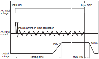
Note: Twice the normal input current will flow for a redundant system. Sufficiently check the fusing characteristics of fuses and the operating characteristics of breakers and select fuses and breakers so that external fuses will not burn out or breakers will not operate due to inrush current.
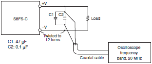
Ripple Noise Voltage
The specified standard for the ripple voltage noise was measured with the following measurement circuit.
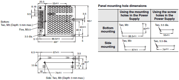
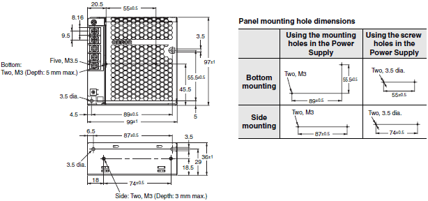
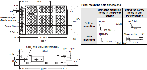
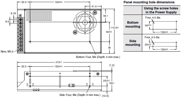
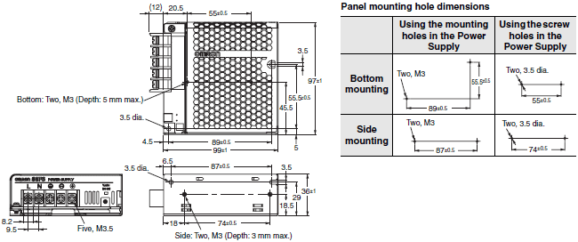
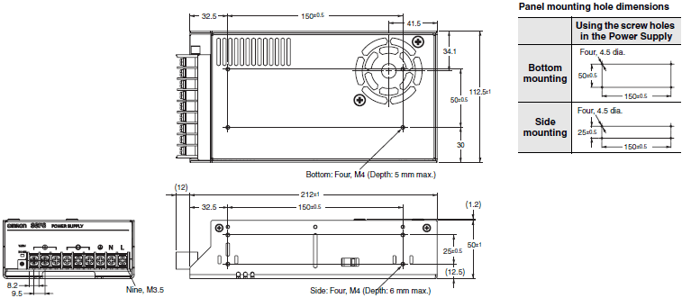
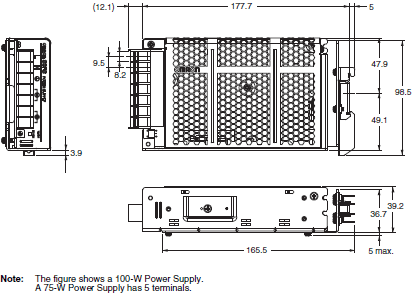
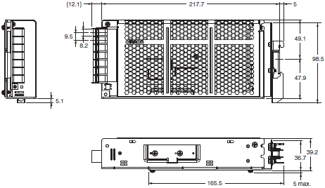
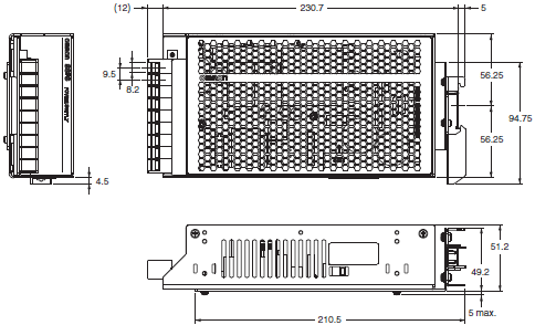
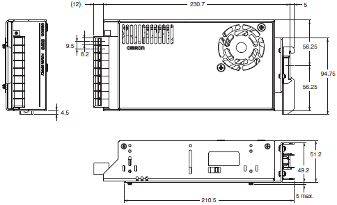
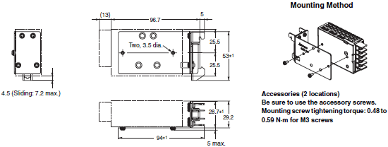
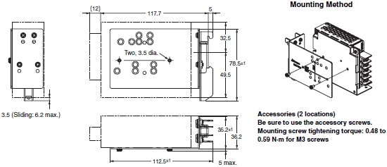
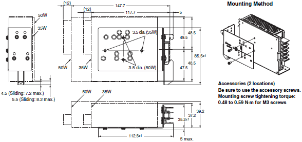
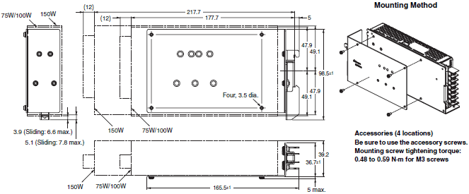
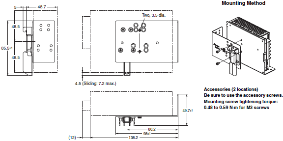
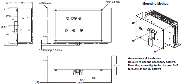
Dimensions | Power Supplies - S8FS-C
Power Supplies
Models with Terminal Block Facing Upward
S8FS-C025[][] (25 W)
S8FS-C035[][] (35 W)
S8FS-C050[][] (50 W)
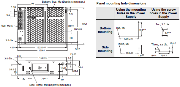
S8FS-C075[][] (75 W)
S8FS-C100[][] (100 W)
Note: The figure shows a 100-W Power Supply.
A 75-W Power Supply has 5 terminals.
S8FS-C150[][] (150 W)
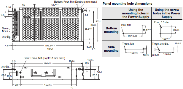
S8FS-C200[][] (200 W)
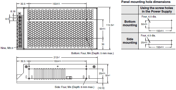
S8FS-C350[][] (350 W)
Models with Terminal Block Facing Forward
S8FS-C015[][]J (15 W)
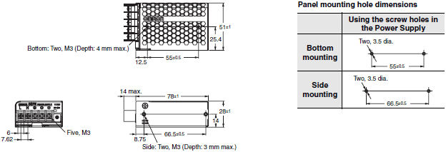
S8FS-C025[][]J (25 W)
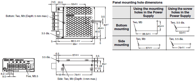
S8FS-C035[][]J (35 W)
S8FS-C050[][]J (50 W)
S8FS-C075[][]J (75 W)
S8FS-C100[][]J (100 W)
S8FS-C150[][]J (150 W)
S8FS-C200[][]J (200 W)
S8FS-C350[][]J (350 W)
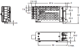
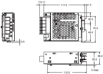
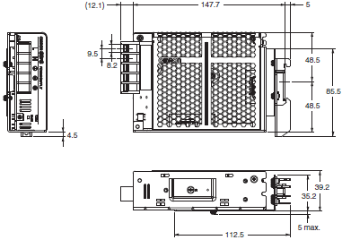
Models with DIN rail
S8FS-C015[][]D (15 W)
S8FS-C025[][]D (25 W)
S8FS-C035[][]D (35 W)

S8FS-C050[][]D (50 W)
S8FS-C075[][]D (75 W)
S8FS-C100[][]D (100 W)
S8FS-C150[][]D (150 W)
S8FS-C200[][]D (200 W)
S8FS-C350[][]D (350 W)
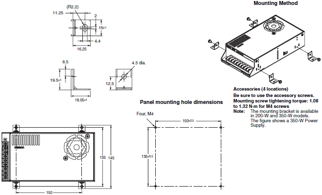
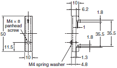
Mounting Brackets
S82Y-FSC015DIN
S82Y-FSC025DIN
S82Y-FSC050DIN
S82Y-FSC150DIN
S82Y-FSC350DIN
S82Y-FSC015DIN-S
S82Y-FSC025DIN-S
S82Y-FSC035DIN-S
S82Y-FSC050DIN-S
S82Y-FSC100DIN-S
S82Y-FSC150DIN-S
S82Y-FSC350B (Four Brackets)
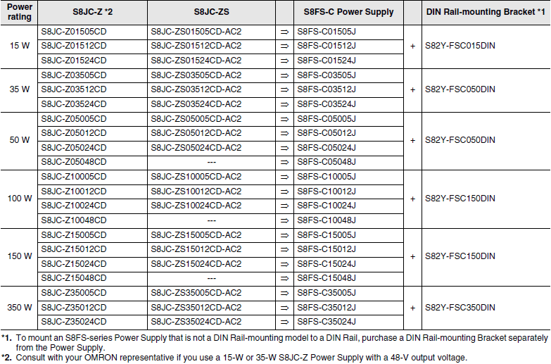
For Users of S8JC DIN Rail-mounting Power Supplies
If you are using a DIN Rail-mounting S8JC-series Power Supply, you can use a DIN Rail-mounting S8FS-C-series Power Supply or replace it with an S8FS-C-series Power Supply with a Forward-facing Terminal Block and a DIN Rail Mounting Bracket.
Table of Corresponding S8JC Power Supplies and S8FS-C[]J Power Supplies with DIN Rail Mounting Brackets
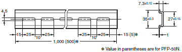
DIN Rail
Mounting Rail (Material: Aluminum)
PFP-100N
PFP-50N
PFP-100N2
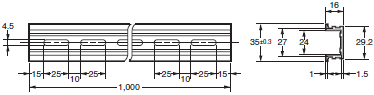
End Plate
PFP-M
Features | Power Supplies - S8FS-C
High Reliability at a Reasonable Cost. Reliable, Basic Power Supplies That Contribute to Stable Equipment Operation.
Properties | Power Supplies - S8FS-C
| Power Supplies | S8FS-C | ||
|---|---|---|---|
| Output | 5 - 48 VDC | ||
| Input | 1-phase 85 - 240 VAC, 120 - 370 VDC (15, 25, 35, 50, 75 W) | ||
| 1-phase 85 - 132 VAC, 176 - 264 VAC, 248 - 373 VDC (100W) | |||
| 1-phase 90 - 132 VAC, 1-phase 180 - 264 VAC, 254 - 373 VDC (150, 200, 350 W) | |||
| Rated voltage | 15 - 350 W | ||
| Current | 0.7 - 60 A | ||
| Weight (g) | 150 - 800 | ||
| Size (W x L x H) mm |
Front-mounting | S8FS C025[][] (25W) | 35 x 99 x 82 |
| S8FS C035[][] (35W) | 35 x 99 x 97 | ||
| S8FS C050[][] (50W) | 38 x 129 x 97 | ||
| S8FS C075[][] (75W) S8FS C100[][] (100W) |
38 x 159 x 97 | ||
| S8FS C150[][] (150W) | 38 x 199 x 97 | ||
| S8FS C200[][] (200W) | 50 x 212 x 112.5 | ||
| S8FS C350[][] (350W) | 50 x 212 x 112.5 | ||
| connector panel facing the front | S8FS C015[][]J (15W) | 51 x 75 x 28 | |
| S8FS C025[][]J (25W) | 82 x 99 x 35 | ||
| S8FS C035[][]J (35W) | 97 x 99 x 36 | ||
| S8FS C050[][]J (50W) | 97 x 129 x 38 | ||
| S8FS C075[][]J (75W) S8FS C100[][]J (100W) |
97 x 159 x 38 | ||
| S8FS C150[][]J (150W) | 97 x 199 x 38 | ||
| S8FS C200[][]J (200W) | 112.5 x 212 x 50 | ||
| S8FS C350[][]J (350W) | 112.5 x 212 x 50 | ||
| DIN-rail | S8FS C015[][]D (15W) | 29.5 x 97.4 x 53 | |
| S8FS C025[][]D (25W) | 36.2 x 117.5 x 82 | ||
| S8FS C035[][]D (35W) | 37.2 x 117.5 x 97 | ||
| S8FS C050[][]D (50W) | 39.2 x 147.7 x 97 | ||
| S8FS C075[][]D (75W) S8FS C100[][]D (100W) |
39.2 x 147.7 x 97 | ||
| S8FS C150[][]D (150W) | 39.2 x 217.7 x 98.5 | ||
| S8FS C200[][]D (200W) | 51.2 x 230.7 x 112.5 | ||
| S8FS C350[][]D (350W) | 51.2 x 230.7 x 112.5 | ||
Power Supplies - S8FS-C
ดาวน์โหลดไฟล์ PDF คุณสมบัติ | Power Supplies - S8FS-C
F8FS-C ของแหล่งจ่ายไฟโหมดสวิตซ์ (Switch Mode Power Supply) เป็นแหล่งจ่ายไฟพื้นฐานที่เชื่อถือได้ พร้อมความต้านทานแรงดันไฟฟ้าเกิดผิดปกติที่เพิ่มขึ้น พร้อมระบบป้องกันไฟกระชากที่ลดลงทำให้การทำงานมีเสถียรภาพ ตัวเก็บประจุด้วยไฟฟ้าที่มีคุณภาพ มีอายุใช้งานที่ยาวนานกว่ารุ่นก่อนหน้าถึง 4 เท่า ซึ่งช่วยเพิ่มความคุ้มค่าให้กับอุปกรณ์จ่ายไฟชุดนี้ รุ่นนี้ติดตั้งราง DIN ได้ง่ายและรวดเร็ว ครอบคลุมช่วงแรงดันไฟฟ้าอินพุตตั้งแต่ 100 - 240 VAC และ 200 - 240 VAC
ข้อมูลจำเพาะ | Power Supplies - S8FS-C
| Power Supplies | S8FS-C | ||
|---|---|---|---|
| เอาต์พุต | 5 - 48 VDC | ||
| อินพุต | 1 เฟส 85 - 240 VAC, 120 - 370 VDC (15, 25, 35, 50, 75 W) | ||
| 1 เฟส 85 - 132 VAC, 176 - 264 VAC, 248 - 373 VDC (100W) | |||
| 1 เฟส 90 - 132 VAC, 1 เฟส 180 - 264 VAC, 254 - 373 VDC (150, 200, 350 W) | |||
| พิกัดกำลังไฟ | 15 - 350 W | ||
| พิกัดกระแอเอาต์พุต | 0.7 - 60 A | ||
| น้ำหนัก | 150 - 800 g | ||
| ขนาด (W x L x H) mm |
รุ่นที่มีแผงขั้วต่อหันขึ้นด้านบน | S8FS C025[][] (25W) | 35 x 99 x 82 |
| S8FS C035[][] (35W) | 35 x 99 x 97 | ||
| S8FS C050[][] (50W) | 38 x 129 x 97 | ||
| S8FS C075[][] (75W) S8FS C100[][] (100W) |
38 x 159 x 97 | ||
| S8FS C150[][] (150W) | 38 x 199 x 97 | ||
| S8FS C200[][] (200W) | 50 x 212 x 112.5 | ||
| S8FS C350[][] (350W) | 50 x 212 x 112.5 | ||
| รุ่นที่มีแผงขั้วต่อหันไปด้านหน้า | S8FS C015[][]J (15W) | 51 x 75 x 28 | |
| S8FS C025[][]J (25W) | 82 x 99 x 35 | ||
| S8FS C035[][]J (35W) | 97 x 99 x 36 | ||
| S8FS C050[][]J (50W) | 97 x 129 x 38 | ||
| S8FS C075[][]J (75W) S8FS C100[][]J (100W) |
97 x 159 x 38 | ||
| S8FS C150[][]J (150W) | 97 x 199 x 38 | ||
| S8FS C200[][]J (200W) | 112.5 x 212 x 50 | ||
| S8FS C350[][]J (350W) | 112.5 x 212 x 50 | ||
| รุ่นที่มีราง DIN | S8FS C015[][]D (15W) | 29.5 x 97.4 x 53 | |
| S8FS C025[][]D (25W) | 36.2 x 117.5 x 82 | ||
| S8FS C035[][]D (35W) | 37.2 x 117.5 x 97 | ||
| S8FS C050[][]D (50W) | 39.2 x 147.7 x 97 | ||
| S8FS C075[][]D (75W) S8FS C100[][]D (100W) |
39.2 x 147.7 x 97 | ||
| S8FS C150[][]D (150W) | 39.2 x 217.7 x 98.5 | ||
| S8FS C200[][]D (200W) | 51.2 x 230.7 x 112.5 | ||
| S8FS C350[][]D (350W) | 51.2 x 230.7 x 112.5 | ||


 Your Lift