
Hydraulic cylinder, mill type รุ่น CSH1
Hydraulic cylinder, Mill type cylinder
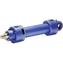
รายละเอียด Hydraulic cylinder, mill type รุ่น CSH1
- Series H1
- Component series 3X
- Nominal pressure 250 bar
- Piston Ø 40 … 320 mm
- Piston rod Ø 22 … 220 mm
- Stroke length up to 6000 mm
Features
- 6 types of mounting
- Self-adjusting and adjustable end position cushioning
Type code
| 01 | 02 | 03 | 04 | 05 | 06 | 07 | 08 | 09 | 10 | 11 | 12 | 13 | 14 | 15 | 16 | ||||
|---|---|---|---|---|---|---|---|---|---|---|---|---|---|---|---|---|---|---|---|
| CS | H1 | / | / | / | A | 3X | / | Z |
| 01 | Single rod cylinder with position measurement system | CS 18) | |
| 02 | Series | H1 | |
| Types of mounting | |||
|---|---|---|---|
| 03 | Swivel eye at cylinder base | MP3 1) | |
| Self-aligning clevis at cylinder base | MP5 | ||
| Round flange at the cylinder head | MF3 | ||
| Round flange at the cylinder base | MF4 | ||
| Trunnion | MT4 2) | ||
| Foot mounting | MS2 | ||
| 04 | Piston Ø (ØAL) 40 … 320 mm | ... | |
| 05 | Piston rod Ø (ØMM) 22 … 220 mm | ... | |
| 06 | Stroke length in mm3) | ... | |
| Design principle | |||
| 07 | Head and base flanged | A | |
| 08 | Component series 30 … 39 (30 … 39: unchanged installation and connection dimensions) | 3X | |
| Line connection / version | |||
| 09 | According to ISO 1179-1 (pipe thread ISO 228-1) | B | |
| According to ISO 9974-1 (metric thread ISO 261) | M | ||
| Flange connection according to ISO 6162-2 tab. 2 type 1 (≙ SAE 6000 PSI) | D 4; 9) | ||
| Flange connection according to ISO 6164 tab. 2 | H 4) | ||
| according to ISO 1179-1 (pipe thread ISO 228-1) with flat pipe flange | C 31) | ||
| For directional and high-response valves | Subplate NG6 | P4; 5) | |
| Subplate NG10 | T4; 6) | ||
| Subplate NG16 | U4; 7) | ||
| Subplate NG25 | V4; 8) | ||
| For SL and SV valves | Subplate NG6 | A4; 5; 15) | |
| Subplate NG10 | E4; 6; 15) | ||
| Subplate NG20 | L4; 7; 15) | ||
| Subplate NG30 | N4; 8; 15) | ||
| Line connection/position at cylinder head | |||
| 10 | View to piston rod30) | 1 | |
| 2 | |||
| 3 | |||
| 4 | |||
| Line connection/position at cylinder base | |||
| 11 | View to piston rod30) | 1 | |
| 2 34) | |||
| 3 | |||
| 4 34) | |||
| Piston rod design | |||
| 12 | Hard chromium-plated | C | |
| Hardened and hard chromium-plated | H 12) | ||
| Nickel-plated and hard chromium-plated | N 19) | ||
| Piston rod end | |||
| 13 | Thread for swivel head CGAS | A | |
| Thread for swivel head CGA, CGAK, plain clevis CSA | G 13) | ||
| With mounted swivel head CGAS | S | ||
| With mounted swivel head CGA | L 13) | ||
| With mounted swivel head CGAK | M 13) | ||
| With mounted swivel head CSA | N 1) | ||
| End position cushioning | |||
| 14 | Without end position cushioning | U | |
| Both sides, adjustable | E 20) | ||
| Seal design | |||
| 15 | For mineral oil HL, HLP and oil-in-water emulsion HFA | Standard seal system | M 29) |
| Standard seal system with guide rings | L | ||
| Reduced friction heavy industry |
R 29) | ||
| For mineral oil HL, HLP, oil-in-water emulsion HFA and water glycol HFC | Standard seal system HFC | G 29) | |
| Servo quality/reduced friction | T 29) | ||
| For HDFR phosphate ester and HFDU polyol ester | Servo quality/reduced friction | S 29) | |
| Standard seal system FKM | V 29) | ||
| Option | |||
| 16 | Additional options, fill fields for additional options | Z | |
| Fields for additional options | ||||||||
|---|---|---|---|---|---|---|---|---|
| 17 | 18 | 19 | 20 | 21 | ||||
| Z | -P 38) | |||||||
| 17 | Position measurement system, magnetostrictive without mating connector, mating connector ‒ separate order, see Technical data | T | ||||||
| 18 | Analog output 4 … 20 mA | C | ||||||
| Analog output 0 … 10 V | F | |||||||
| Digital output SSI | D | |||||||
| Profibus D63 | N | |||||||
| Profibus D53 | P | |||||||
| 19 | Measuring coupling, on both sides | A | ||||||
| Without measuring coupling | W | |||||||
| 20 | Spherical bearing, maintenance-free | A14; 35) | ||||||
| Flanged grease nipple | B | |||||||
| Standard conical grease nipple | W | |||||||
| 21 | Piston rod extension “LY”, specify in mmin plain text | Y | ||||||
| Without piston rod extension | W | |||||||
- Only piston Ø 40 … 200 mm
- Trunnion position freely selectable. When ordering, always specify the "XV" dimensions in the plain text in
- For max. available stroke length see Technical data and for admissible stroke length (according to the kinking calculation) see Project planning information.
- Not possible with MF4
- Piston Ø 40 … 80 mm, only position 11, subplates only possible in combination with line connection “B” at the head
- Piston Ø 63 … 200 mm, only position 11, subplates only possible in combination with line connection “B” at the head
- Piston Ø 125 … 200 mm, only position 11, subplates only possible in combination with line connection “B” at the head
- Only piston Ø 160 … 200 mm, only position 11, subplates only possible in combination with line connection “B” at the head
- Only piston Ø 80 … 320 mm
- 12) Only piston rod Ø 22 … 140 mm
- 13) Not with piston Ø 320 mm
- 14) Not possible with piston rod end "N"
- 15) Subplates for SL and SV valves (isolator valves) Please note: Seal designs T, G, L, R, S and V are not designed for the static holding function!
- 18) Not standardized
- 19) Only piston rod Ø 28 … 160 mm
- 20) Possible from piston rod Ø 45 mm
- 29) With CSH, by default with guide belts
- 30) All graphical representations in the data sheet show position 1
- 31) With MS2, only position 11 is possible
- 34) With MF4 and line connection B, M or C not possible
- 35) Not possible with MP3
- 38) Marks order-relevant information which cannot be represented in the ordering code. These must be specified for each order.
Order example:
CSH1MP5/100/56/300A3X/T11CAEMZ TCAWW
With order-relevant information:
CSH1MP5/100/56/300A3X/T11CAEMZ TCAWW-P
Data Sheet : Hydraulic cylinder, mill type รุ่น CSH1


 Your Lift