| 01 |
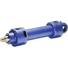
Single rod cylinder |
CD |
| 02 |
Series |
M1 |
| Types of mounting |
|---|
| 03 |
Without mounting |
M00 1) |
| Rectangular flange at cylinder head |
MF1 2) |
| Rectangular flange at cylinder base |
MF2 2) |
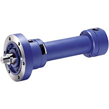
| Round flange at the cylinder head |
MF3 |
| Round flange at the cylinder base |
MF4 |
| Swivel eye at cylinder base |
MP3 |
| Self-aligning clevis at cylinder base |
MP5 |
| Trunnion |
MT4 3) |
| Foot mounting |
MS2 |
| 04 |
Piston Ø (ØAL) from 25 … 200 mm; see Technical data |
... |
| 05 |
Piston rod Ø (ØMM) 14 … 140 mm; see Technical data |
... |
| 06 |
Stroke length in mm |
... |
| Design principle |
|---|
| 07 |
Head and base flanged |
A |
| 08 |
Component series 20 … 29 (20 … 29: unchanged installation and connection dimensions) |
2X |
| Line connection / version |
|---|
| 09 |
Pipe thread according to ISO 1179-1 |
B |
| Metric ISO thread (DIN/ISO 6149-1) |
R |
| Enlarged pipe thread according to ISO 1179-1; see Dimensions |
S4;5) |
| Rectangular flange connection according to ISO 6162; see Dimensions |
F5;6) |
| Square flange connection according to ISO 6164; see Dimensions |
H5;7) |
| For directional and high-response valves; see Dimensions |
Subplate NG6 |
P5;8;13) |
| Subplate NG10 |
T5;9;13) |
| Subplate NG16 |
U5;10;13) |
| For SL and SV valves14); see Dimensions |
Subplate NG6 |
A5;8;13) |
| Subplate NG10 |
E5;9;13) |
| Subplate NG20 |
L5;10;13) |
| Line connection/position at cylinder head |
|---|
| 10 |
View to piston rod16) |
|
1 |
| 2 |
| 3 |
| 4 |
| Line connection/position at cylinder base |
|---|
| 11 |
View to piston rod16) |
|
1 |
| 2 |
| 3 |
| 4 |
| Piston rod design |
|---|
| 12 |
Hard chromium-plated |
C |
| Hardened and hard chromium-plated |
H 11) |
| Stainless steel, hard chromium-plated |
L |
| Piston rod end |
|---|
| 13 |
Thread (ISO 6020-1) for swivel head CGKD |
G |
| Thread (VW standard) for swivel head CGKD |
H 15) |
| Internal thread; see dimensions |
E 12) |
| Piston rod end “H” with mounted swivel head CGKD |
F 15) |
| Piston rod end “G” with mounted swivel head CGKD |
K |
| End position cushioning |
|---|
| 14 |
Without end position cushioning |
U |
| Both sides, self-adjusting |
D |
| Head sides, self-adjusting |
S |
| Base sides, self-adjusting |
K |
| Both sides, adjustable |
E |
| Seal design |
|---|
| 15 |
Suitable for mineral oil according to DIN 51524 HL, HLP |
Standard seal system |
M |
| Servo quality/reduced friction |
T 7) |
| Chevron seal kits |
A 6) |
| Suitable for phosphoric acid esters HFR |
Standard seal system |
V |
| Servo quality/reduced friction |
S 7) |
| Option 1 |
|---|
| 16 |
Without option |
W |
| Measuring coupling, on both sides |
A |
| Inductive proximity switches without mating connector, mating connector – separate order; see Accessories |
E 7) |
| Option 2 |
|---|
| 17 |
Without option |
W |
| With piston rod extension “LY” in mm |
Y 17) |


 Your Lift