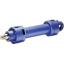
CG SERIES : REXROTH HYDRAULIC CYLIDER MILL TYPE

Rexroth Hydraulic Cylinder - Mill Type Cylinder รุ่น CG Series กระบอกไฮดรอลิก แบบกระบอกกลม ทำงานทนทานกว่า สินค้าอุปกรณ์ไฮดรอลิกจาก Rexroth สินค้ามาตรฐานโลก ระดับสากล จัดจำหน่ายโดย นิวแอนด์ไฮด์ จำกัด

  • Rexroth Mill Type Cylinder รุ่น CG Series

    รุ่น CGH1

    1. Series H1
    2. Component series 3X
    3. Nominal pressure 250 bar
    4. Piston Ø 40 … 320 mm
    5. Piston rod Ø 22 … 220 mm
    6. Stroke length up to 6000 mm
  • Rexroth Mill Type Cylinder รุ่น CG Series

    รุ่น CGH2

    1. Series H2
    2. Component series 3X
    3. Nominal pressure 250 bar
    4. Piston Ø 40 … 320 mm
    5. Piston rod Ø 25 … 220 mm
    6. Stroke length up to 6000 mm
  • Rexroth Mill Type Cylinder รุ่น CG Series

    รุ่น CGH2...XC

    1. Series H2
    2. Component series 3X
    3. Nominal pressure 250 bar
    4. Piston Ø 40 … 320 mm
    5. Piston rod Ø 25 … 220 mm
    6. Stroke length up to 6000 mm
  • Rexroth Mill Type Cylinder รุ่น CG Series

    รุ่น CGH3

    1. Series H3
    2. Component series 3X
    3. Nominal pressure 350 bar
    4. Piston Ø 40 … 320 mm
    5. Piston rod Ø 28 … 220 mm
    6. Stroke length up to 6000 mm
  • Rexroth Mill Type Cylinder รุ่น CG Series

    รุ่น CGM1

    1. Series M1
    2. Component series 2X
    3. Nominal pressure 160 bar
    4. Piston Ø 25 … 200 mm
    5. Piston rod Ø 14 … 140 mm
    6. Stroke length up to 3000 mm

Hydraulic cylinder, mill type รุ่น CGH1

Hydraulic cylinder, Mill type cylinder

CD CG CS
Hydraulic cylinder รุ่น CGH1

รายละเอียด Hydraulic cylinder, mill type รุ่น CGH1

  • Series H1
  • Component series 3X
  • Nominal pressure 250 bar
  • Piston Ø 40 … 320 mm
  • Piston rod Ø 22 … 220 mm
  • Stroke length up to 6000 mm

Features

  • 3 types of mounting
  • Self-adjusting and adjustable end position cushioning

Type code

010203 04 05 060708 0910111213141516
CG H1   /   /   /   A 3X /                

01 Double rod cylinder CG 18)
02 Series H1
Types of mounting
03 Round flange at the cylinder head MF3
Trunnion MT4 2)
Foot mounting MS2
04 Piston Ø (ØAL) 40 … 320 mm ...
05 Piston rod Ø (ØMM) 22 … 220 mm ...
06 Stroke length in mm3) ...
Design principle
07 Head and base flanged A
08 Component series 30 … 39 (30 … 39: unchanged installation and connection dimensions) 3X
Line connection / version
09 According to ISO 1179-1 (pipe thread ISO 228-1) B
According to ISO 9974-1 (metric thread ISO 261) M
Flange connection according to ISO 6162-2 tab. 2 type 1 (≙ SAE 6000 PSI) D 9)
Flange connection according to ISO 6164 tab. 2 H
according to ISO 1179-1 (pipe thread ISO 228-1) with flat pipe flange C 31)
Line connection/position at cylinder head
10 View to piston rod30) cd cg cs symbol1 01 1
2
3
4
Line connection/position at cylinder base
11 View to piston rod30) cd cg cs symbol1 02 1
2
3
4
Piston rod design
12 Hard chromium-plated C
Hardened and hard chromium-plated H 12)
Piston rod end
13 Thread for swivel head CGAS A
Thread for swivel head CGA, CGAK, plain clevis CSA G 13)
With mounted swivel head CGAS S 17)
With mounted swivel head CGA L13; 17)
With mounted swivel head CGAK M13; 17)
With mounted swivel head CSA N1; 17)
End position cushioning
14 Without end position cushioning U
Both sides, self-adjusting D 1)
Both sides, adjustable E
Seal design
15 For mineral oil HL, HLP and oil-in-water emulsion HFA Standard seal system M
Standard seal system with guide rings L
Reduced friction
heavy industry
R
For mineral oil HL, HLP, oil-in-water emulsion HFA and water glycol HFC Standard seal system HFC G
Servo quality/reduced friction T
Chevron seal kits A
For HDFR phosphate ester and HFDU polyol ester Servo quality/reduced friction S
Standard seal system FKM V
Chevron seal kits B
Option
16 Additional options, fill fields for additional options Z
Without additional options, do not fill fields for additional options W
Fields for additional options
    17 18 19 20 21  
Z           -P 38)
17 Inductive proximity switches without mating connector - separate order E 37)
Without inductive proximity switches W
18 Additional guide rings F10; 28)
Without additional guide rings W
19 Measuring coupling, on both sides A
Without measuring coupling W
20 Spherical bearing, maintenance-free A14; 35)
Flanged grease nipple B
Standard conical grease nipple W
21 Piston rod extension “LY”, specify in mmin plain text Y 16)
Without piston rod extension W
  • 1) Only piston Ø 40 … 200 mm
  • 2) Trunnion position freely selectable. When ordering, always specify the "XV" dimensions in the plain text in mm
  • 3) For max. available stroke length see Technical data and for admissible stroke length (according to the kinking calculation) see Project planning information.
  • 9) Only piston Ø 80 … 320 mm
  • 10) Seal designs A, B not possible; piston Ø 220 … 320 mm standard
  • 12) Only piston rod Ø 22 … 140 mm
  • 13) Not with piston Ø 320 mm
  • 14) Not possible with piston rod end "N"
  • 16) Only at left piston rod side (orientation: catalog figures)
  • 17) Only one swivel head/plain clevis mounted, left piston rod side (orientation: catalog figures)
  • 18) Not standardized
  • 28) With seal design "L" standard
  • 30) All graphical representations in the data sheet show position 1
  • 35) Not possible with MP3
  • 37) Min. stroke length = 20 mm
  • 38) Marks order-relevant information which cannot be represented in the ordering code. These must be specified for each order.

Order example:
CGH1MF3/100/56/300A3X/B11CADMW
CGH1MF/100/56/300A3X/B11CADMZ EWABW
With order-relevant information:
CGH1MF3/100/56/300A3X/B11CADMW-P
CGH1MF3/100/56/300A3X/B11CADMZ EWABW-P


Hydraulic cylinder, mill type รุ่น CGH2

Hydraulic cylinder, Mill type cylinder

CD CG CS
Hydraulic cylinder, mill type รุ่น CGH2

รายละเอียด Hydraulic cylinder, mill type รุ่น CGH2

  • Series H2
  • Component series 3X
  • Nominal pressure 250 bar
  • Piston Ø 40 … 320 mm
  • Piston rod Ø 25 … 220 mm
  • Stroke length up to 6000 mm

Features

  • Standards: DIN 24333, ISO 6022
  • 3 types of mounting
  • Self-adjusting and adjustable end position cushioning

Type code

010203 04 05 060708 0910111213141516
CG H2   /   /   /   A 3X /                

01 Double-acting cylinder18) CG
02 Series H2
Types of mounting
03 Round flange at the cylinder head MF3
Trunnion MT4 2)
Foot mounting MS2
04 Piston Ø (ØAL) 40 … 320 mm ...
05 Piston rod Ø (ØMM) 25 … 220 mm ...
06 Stroke length in mm3) ...
Design principle
07 Head and base flanged A
08 Component series 30 … 39 (30 … 39: unchanged installation and connection dimensions) 3X
Line connection / version
09 According to ISO 1179-1 (pipe thread ISO 228-1) B
According to ISO 9974-1 (metric thread ISO 261) M 33)
Flange connection according to ISO 6162-1 tab. 2 type 1 (≙ SAE 3000 PSI) F 21)
Flange connection according to ISO 6162-2 tab. 2 type 1 (≙ SAE 6000 PSI) D 9)
Flange connection according to ISO 6164 tab. 1 K 1)
Flange connection according to ISO 6164 tab. 2 H
according to ISO 1179-1 (pipe thread ISO 228-1) with flat pipe flange C 31)
Line connection/position at cylinder head
10 View to piston rod30)  cd cg cs symbol1 01 1
2
3
4
Line connection/position at cylinder base
11 View to piston rod30)  cd cg cs symbol1 02 1
2
3
4
Piston rod design
12 Hard chromium-plated C
Hardened and hard chromium-plated H 23)
Piston rod end
13 Thread for swivel head CGKD H
With mounted swivel head CGKD F 17)
End position cushioning
14 Without end position cushioning U
Both sides, self-adjusting D 1)
Both sides, adjustable E
Seal design
15 For mineral oil HL, HLP and oil-in-water emulsion HFA Standard seal system M
Standard seal system with guide rings L
Reduced friction
heavy industry
R
For mineral oil HL, HLP, oil-in-water emulsion HFA and water glycol HFC Standard seal system HFC G
Servo quality/reduced friction T
Chevron seal kits A
For HDFR phosphate ester and HFDU polyol ester Servo quality/reduced friction S
Standard seal system FKM V
Chevron seal kits B
Option
16 Additional options, fill fields for additional options Z
Without additional options, do not fill fields for additional options W
Fields for additional options
    17 18 19 20 21  
Z           -P 38)
17 Inductive proximity switches without mating connector - separate order E 37)
Without inductive proximity switches W
18 Additional guide rings F10; 28)
Without additional guide rings W
19 Measuring coupling, on both sides A
Without measuring coupling W
20 Flanged grease nipple B
Standard conical grease nipple W
21 Piston rod extension “LY”, specify in mmin plain text Y 16)
Without piston rod extension W
  • 1) Only piston Ø 40 … 200 mm
  • 2) Trunnion position freely selectable. When ordering, always specify the "XV" dimensions in the plain text in mm
  • 3) For max. available stroke length see Technical data and for admissible stroke length (according to the kinking calculation) see Project planning information.
  • 9) Only piston Ø 80 … 320 mm
  • 10) Seal designs A, B not possible; piston Ø 220 … 320 mm standard
  • 16) Only at left piston rod side (orientation: see figures Dimensions)
  • 17) Only one plain clevis / swivel head mounted, left piston rod side (orientation: see figures Accessories)
  • 18) Not standardized
  • 21) Only piston Ø 63 … 200 mm
  • 23) Only piston rod Ø 25 … 140 mm
  • 28) With seal design "L" standard
  • 30) All graphical representations in the data sheet show position 1
  • 31) With MS2, only position 11 is possible
  • 33) Version does not comply with ISO 6022
  • 37) Min. stroke length = 20 mm
  • 38) Marks order-relevant information which cannot be represented in the ordering code. These must be specified for each order.

Order examples:
Without additional options:
CGH2MF3/100/70/500A3X/B11CHUMW
With additional options:
CGH2MF3/100/70/500A3X/B11CHUMZ EWAWW
With order-relevant information:
CGH2MF3/100/70/500A3X/B11CHUMW-P
CGH2MF3/100/70/500A3X/B11CHUMZ EWAWW-P


Hydraulic cylinders รุ่น CGH2...XC

Hydraulic cylinders for potentially explosive areas

CD CG CS
Hydraulic cylinders รุ่น CGH2...XC

รายละเอียด Hydraulic cylinders รุ่น CGH2...XC

  • Series H2
  • Component series 3X
  • Nominal pressure 250 bar
  • Piston Ø 40 … 320 mm
  • Piston rod Ø 25 … 220 mm
  • Stroke length up to 6000 mm

Features

  • Standards: DIN 24333, ISO 6022
  • 3 types of mounting

Type code

010203 04 05 060708 0910111213141516
CG H2   /   /   /   XC 3X /                

01 Double rod cylinder CG 18)
02 Series H2
Types of mounting
03 Round flange at the cylinder head MF3
Trunnion MT4 2)
Foot mounting MS2
04 Piston Ø (ØAL) 40 … 320 mm ...
05 Piston rod Ø (ØMM) 25 … 220 mm ...
06 Stroke length in mm3) ...
Protection class for ATEX version
07 Design safety XC
08 Component series 30 … 39 (30 … 39: unchanged installation and connection dimensions) 3X
Line connection / version
09 According to ISO 1179-1 (pipe thread ISO 228-1) B
According to ISO 9974-1 (metric thread ISO 261) M 33)
Flange connection according to ISO 6162-1 tab. 2 type 1 (≙ SAE 3000 PSI) F 21)
Flange connection according to ISO 6162-2 tab. 2 type 1 (≙ SAE 6000 PSI) D 9)
Flange connection according to ISO 6164 tab. 1 K 4)
Flange connection according to ISO 6164 tab. 2 H
Line connection/position at cylinder head
10 View to piston rod30)  cd cg cs symbol1 01 1
2
3
4
Line connection/position at cylinder base
11 View to piston rod30)  cd cg cs symbol1 02 1
2
3
4
Piston rod design
12 Hard chromium-plated C
Hardened and hard chromium-plated H 23)
Piston rod end
13 Thread for swivel head CGKD H
With mounted swivel head CGKD F 17)
End position cushioning
14 Without end position cushioning U
Both sides, self-adjusting D 1)
Both sides, adjustable E
Seal design
15 For mineral oil HL, HLP and oil-in-water emulsion HFA Standard seal system M
For mineral oil HL, HLP, oil-in-water emulsion HFA and water glycol HFC Servo quality/reduced friction T
Chevron seal kits A
For phosphoric acid esters HFR Servo quality/reduced friction S
Chevron seal kits B
Option
16 Additional options, fill fields for additional options Z
Without additional options, do not fill fields for additional options W
Fields for additional options
    17 18 19 20 21  
Z            
17 Without option W
18 Additional guide rings F 10)
Without additional guide rings W
19 Measuring coupling, on both sides A
Without measuring coupling W
20 Flanged grease nipple B
Standard conical grease nipple W
21 Piston rod extension “LY”, specify in mmin plain text Y 16)
Without piston rod extension W
  • 1) Only piston Ø 40 … 200 mm
  • 2) Trunnion position freely selectable. When ordering, always specify the "XV" dimensions in the plain text in mm
  • 3) For max. available stroke length see Technical data and for admissible stroke length (according to the kinking calculation) see Project planning information.
  • 9) Only piston Ø 80 … 320 mm
  • 10) Seal designs A, B not possible; piston Ø 220 … 320 mm standard
  • 16) Only at left piston rod side (orientation: see figures Dimensions)
  • 17) Only one plain clevis/swivel head mounted, left piston rod side (orientation: see figures Accessories)
  • 18) Not standardized
  • 21) Only piston Ø 63 … 200 mm
  • 23) Only piston rod Ø 25 … 140 mm
  • 30) All graphical representations in the data sheet show position 1
  • 33) Version does not comply with ISO 6022

Order examples:
Without additional options:
CGH2MF3/100/70/500XC3X/B11CHUMWW
With additional options:
CGH2MF3/100/70/500XC3X/B11CHUMZ WWAWW


Hydraulic cylinder, mill type รุ่น CGH3

Hydraulic cylinder, Mill type cylinder

CD CG CS
Hydraulic cylinder, mill type รุ่น CGH3

รายละเอียด Hydraulic cylinder, mill type รุ่น CGH3

  • Series H3
  • Component series 3X
  • Nominal pressure 350 bar
  • Piston Ø 40 … 320 mm
  • Piston rod Ø 28 … 220 mm
  • Stroke length up to 6000 mm

Features

  • 3 types of mounting
  • Self-adjusting and adjustable end position cushioning

Type code

010203 04 05 060708 0910111213141516
CG H3   /   /   /   A 3X /                

01 Double-acting cylinder18) CG
02 Series H3
Types of mounting
03 Round flange at the cylinder head MF3
Trunnion MT4 2)
Foot mounting MS2
04 Piston Ø (ØAL) 40 … 320 mm ...
05 Piston rod Ø (ØMM) 28 … 220 mm ...
06 Stroke length in mm3) ...
Design principle
07 Head and base flanged A
08 Component series 30 … 39 (30 … 39: unchanged installation and connection dimensions) 3X
Line connection / version
09 According to ISO 1179-1 (pipe thread ISO 228-1) B
According to ISO 9974-1 (metric thread ISO 261) M
Flange connection according to ISO 6162-2 tab. 2 type 1 (≙ SAE 6000 PSI) D 25)
Flange connection according to ISO 6164 tab. 2 H
according to ISO 1179-1 (pipe thread ISO 228-1) with flat pipe flange C 31)
Line connection/position at cylinder head
10 View to piston rod30)  cd cg cs symbol1 01 1
2
3
4
Line connection/position at cylinder base
11 View to piston rod30)  cd cg cs symbol1 02 1
2
3
4
Piston rod design
12 Hard chromium-plated C
Hardened and hard chromium-plated H 24)
Piston rod end
13 Thread for swivel head CGKD H
Thread for swivel head CGA, CGAK, plain clevis CSA G 26)
With mounted swivel head CGAS S 17; 26)
With mounted swivel head CGA L 17; 26)
With mounted swivel head CGAK M 17; 26)
With mounted plain clevis CSA N 1; 17)
End position cushioning
14 Without end position cushioning U
Both sides, self-adjusting D 1)
Both sides, adjustable E
Seal design
15 For mineral oil HL, HLP and oil-in-water emulsion HFA Standard seal system M
Standard seal system with guide rings L
Reduced friction
heavy industry
R
For mineral oil HL, HLP, oil-in-water emulsion HFA and water glycol HFC Standard seal system HFC G
Servo quality/reduced friction T
Chevron seal kits A
For HDFR phosphate ester and HFDU polyol ester Servo quality/reduced friction S
Standard seal system FKM V
Chevron seal kits B
Option
16 Additional options, fill fields for additional options Z
Without additional options, do not fill fields for additional options W
Fields for additional options
    17 18 19 20 21  
Z           -P 38)
17 Inductive proximity switches without mating connector - separate order E 37)
Without inductive proximity switches W
18 Additional guide rings F 10; 28)
Without additional guide rings W
19 Measuring coupling, on both sides A
Without measuring coupling W
20 Spherical bearing, maintenance-free A
Flanged grease nipple B
Standard conical grease nipple W
21 Piston rod extension “LY”, specify in mmin plain text Y 16)
Without piston rod extension W
  • 1) Only piston Ø 40 … 200 mm
  • 2) Trunnion position freely selectable. When ordering, always specify the "XV" dimensions in the plain text in mm
  • 3) For max. available stroke length see Technical data and for admissible stroke length (according to the kinking calculation) see Project planning information.
  • 9) Only piston Ø 80 … 320 mm
  • 10) Seal designs A, B not possible; piston Ø 220 … 320 mm standard
  • 14) Not possible with piston rod end "N"
  • 16) Only at left piston rod side (orientation: see figures Dimensions)
  • 17) Only one swivel head/plain clevis mounted, left piston rod side (orientation: see figures Accessories)
  • 18) Not standardized
  • 24) Only piston rod Ø 28 … 140 mm
  • 25) Only piston Ø 63 … 320 mm
  • 26) Only piston Ø 40 … 250 mm
  • 27) Maximum operatign pressure 315 bar
  • 28) With seal design "L" standard
  • 30) All graphical representations in the data sheet show position 1
  • 31) With MS2, only position 11 is possible
  • 33) Version does not comply with ISO 6022
  • 37) Min. stroke length = 20 mm
  • 38) Marks order-relevant information which cannot be represented in the ordering code. These must be specified for each order.

Order example:
Without additional options:
CGH3MF3/100/56/300A3X/B11CADMW
With additional options:
CGHMF3/100/56/300A3X/B11CADMZ EWABW

With order-relevant information: CGH3MF3/100/56/300A3X/B11CADMW-P
CGHMF3/100/56/300A3X/B11CADMZ EWABW-P


Hydraulic cylinder, mill type รุ่น CGM1

Hydraulic cylinder, Mill type cylinder

CD CG CS
Hydraulic cylinder, mill type รุ่น CGM1

รายละเอียด Hydraulic cylinder, mill type รุ่น CGM1

  • Series M1
  • Component series 2X
  • Nominal pressure 160 bar
  • Piston Ø 25 … 200 mm
  • Piston rod Ø 14 … 140 mm
  • Stroke length up to 3000 mm

Features

  • Installation dimensions according to ISO 6020/1 and VW 39 D 920
  • 4 types of mounting
  • Self-adjusting and adjustable end position cushioning

Type code

010203 04 05 060708 091011121314151617
CG M1   /   /   /   A 2X /                  

01 Double rod cylinder CG 1)
02 Series M1
Types of mounting
03 Rectangular flange at cylinder head MF1 2)
Round flange at the cylinder head MF3
Trunnion MT4 3)
Foot mounting MS2
04 Piston Ø (ØAL) from 25 … 200 mm; see Technical data ...
05 Piston rod Ø (ØMM) 14 … 140 mm; see Technical data ...
06 Stroke length in mm ...
Design principle
07 Head and base flanged A
08 Component series 20 … 29 (20 … 29: unchanged installation and connection dimensions) 2X
Line connection / version
09 Pipe thread according to ISO 1179-1 B
Metric ISO thread (DIN/ISO 6149-1) R
Enlarged pipe thread according to ISO 1179-1; see Dimensions S 4)
Rectangular flange connection according to ISO 6162; see Dimensions F 5)
Square flange connection according to ISO 6164; see Dimensions H 6)
For directional and high-response valves; see Dimensions Subplate NG6 P 7;11)
Subplate NG10 T 8;11)
Subplate NG16 U 9;11)
For SL and SV valves12); see Dimensions Subplate NG6 A 7;11)
Subplate NG10 E 8;11)
Subplate NG20 L 9;11)
Line connection/position at cylinder head
10 View to piston rod14)  cd cg cs symbol1 01 1
2
3
4
Line connection/position at cylinder base
11 View to piston rod14)  cd cg cs symbol1 02 1
2
3
4
Piston rod design
12 Hard chromium-plated C
Hardened and hard chromium-plated H 10)
Stainless steel, hard chromium-plated L
Piston rod end
13 Thread (ISO 6020-1) for swivel head CGKD G
Thread (VW standard) for swivel head CGKD H 13)
Piston rod end “H” with mounted swivel head CGKD F 13)
Piston rod end “G” with mounted swivel head CGKD K
End position cushioning
14 Without end position cushioning U
Both sides, self-adjusting D
Both sides, adjustable E
Seal design
15 Suitable for mineral oil according to DIN 51524 HL, HLP Standard seal system M
Servo quality/reduced friction T 6)
Chevron seal kits A 5)
Suitable for phosphoric acid esters HFR Standard seal system V
Servo quality/reduced friction S 6)
Option 1
16 Without option W
Measuring coupling, on both sides A
Inductive proximity switches without mating connector, mating connector – separate order; see Accessories E 6)
Option 2
17 Without option W
With piston rod extension “LY” in mm Y
  • 1) Not standardized
  • 2) Piston Ø 25 … 125 mm
  • 3) When ordering, always specify the "XV" dimension in the plain text in mm (see order example)
  • 4) Piston Ø 63 … 200 mm
  • 5) Piston Ø 50 … 200 mm
  • 6) Piston Ø 40 … 200 mm
  • 7) Piston Ø 40 … 80 mm, only position 11
  • 8) Piston Ø 63 … 200 mm, only position 11
  • 9) Piston Ø 125 … 200 mm, only position 11
  • 10) Piston rod Ø 14 … 110 mm
  • 11) Subplates only possible with pipe thread (ISO 1179-1)
  • 12) Subplates for SL and SV valves (isolator valves)
  • Please note: Seal designs T and S are not designed for the static holding function!
  • 13) Per piston Ø only possible with large piston rod Ø
  • 14) All graphical representations in the data sheet show position 1

Order example:
CDM1MT4/50/28/550A2X/B11CGDMWW, XV = 175 mm
CDM1MF3/200/140/950A2X/B11CHKAWW
Note:
Replacement cylinder for series 1X
In case of exchange with series 2X, you also have to exchange the bearing blocks (trunnions)!


ติดต่อ Rexroth / งานโปรเจ็ค / กระบอกไฮดรอลิก / งานซ่อม และงานบริการ

Rexroth contact
ดาว์นโหลด แคตตาล็อก, สเป้กแอร์แทค
Promotion-Big Sale
ติดต่อเรา
TICTechnology Instrument 
www.tic.co.th
tupackT.U Pack 
www.tupack.co.th
Your LiftYour Lift 
www.yourlift.co.th