
Hydraulic cylinder รุ่น CG70
Hydraulic cylinder tie rod design
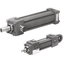
รายละเอียด Hydraulic cylinder รุ่น CG70
- Series 70
- Component series 1X
- Nominal pressure 70 bar
- Piston Ø 25 … 200 mm
- Piston rod Ø 12 … 140 mm
- Stroke length up to 3000 mm
Features
- 9 types of mounting
Type code
| 01 | 02 | 03 | 04 | 05 | 06 | 07 | 08 | 09 | 10 | 11 | 12 | 13 | 14 | 15 | 16 | 17 | 18 | ||||
|---|---|---|---|---|---|---|---|---|---|---|---|---|---|---|---|---|---|---|---|---|---|
| CG | 70 | / | — | Z | 1X | / | — | * |
| 01 | Double rod cylinder | CG | |
| 02 | Series | 70 | |
| Types of mounting | |||
|---|---|---|---|
| 03 | Rectangular flange at cylinder head | C 2) | |
| Square flange at cylinder head | H | ||
| Trunnion at cylinder head | R 1) | ||
| Trunnion in cylinder center | E 3) | ||
| Foot mounting | F | ||
| Foot mounting with fitting key | L 2) | ||
| Foot mounting with seal ring sealing for subplate mounting | M | ||
| Tapped holes in cylinder head and base | N | ||
| Extended tie rod at cylinder head | P | ||
| 04 | Piston Ø (ØAL) 25 … 200 mm | ... | |
| 05 | Piston rod Ø (ØMM) 12 … 140 mm | ... | |
| 06 | Stroke length in mm4) | ... | |
| Design principle | |||
| 07 | Cylinder head and cylinder base connected by tie rod | Z | |
| 08 | Component series 11 … 19 (11 … 19: unchanged installation and connection dimensions) | 1X | |
| Line connection / version | |||
| 09 | Flange connection with seal ring sealing; only possible with “M” type of mounting | 00 | |
| Pipe thread according to ISO 228/1 | 01 10) | ||
| Metric ISO thread | 02 10) | ||
| Enlarged line connection; pipe thread according to ISO 228/1 | 13 5; 10) | ||
| Enlarged line connection; metric ISO thread | 14 5; 10) | ||
| Piston rod design | |||
| 10 | Hardened and hard chromium-plated | H | |
| Hard chromium-plated, from piston Ø ≥ 80 mm | C 6) | ||
| Piston rod end | |||
| 11 | external thread | B | |
| external thread | C | ||
| Internal thread | E 7) | ||
| Thread for swivel head | F | ||
| With mounted swivel head CGK | T | ||
| End position cushioning | |||
| 12 | Without | U | |
| Base side | K | ||
| Head side | S | ||
| Both sides | D | ||
| Hydraulic fluid | |||
| 13 | Seals, suitable for mineral oil according to DIN 51524 (HL, HLP) | M | |
| FKM seals suitable for phosphate ester (HFDR) | V | ||
| Line connection/position at cylinder head | |||
| 14 | Enter position; observe the “position of the line connections” notices! View to piston rod8) |  |
1 |
| 2 | |||
| 3 | |||
| 4 | |||
| Line connection/position at cylinder base | |||
| 15 | Enter position; observe the “position of the line connections” notices! View to piston rod8) |  |
1 |
| 2 | |||
| 3 | |||
| 4 | |||
| Seals | |||
| 16 | Standard version | A | |
| Design for low-friction operation | T | ||
| 17 | Enter support width extension | … | |
| 18 | Further details in the plain text 9) | * | |
- 1) Not possible for piston Ø 25 mm0.98 in
- 2) Not possible for piston Ø 200 mm7.87 in
- 3) Position of trunnion freely selectable. When ordering, always specify the dimension "XV" in the plain text in mminch. With piston Ø 25 mm0.98 in, the trunnions are at the cylinder head.
- 4) Observe the admissible stroke length, see “Admissible stroke lengths” in the project planning information.
- 5) See dimensions.
- 6) Not possible with piston rod end “E”.
- 7) Not possible with piston rod Ø 12 mm0.47 in.
- 8) All graphical representations in the data sheet show position 1.
- 9) Always specify the attachment of inductive proximity switches or piston rod extensions “LY” in the order in the plain text.
- 10) Not possible with type of mounting “M”.
Order example:
G70C50/22-200Z1X/01HBDM1-1A
With special versions, an “X” will be inserted in the type key at the corresponding position and an SO number will be amended at the end.
Data Sheet : Hydraulic cylinder รุ่น CG70


 Your Lift