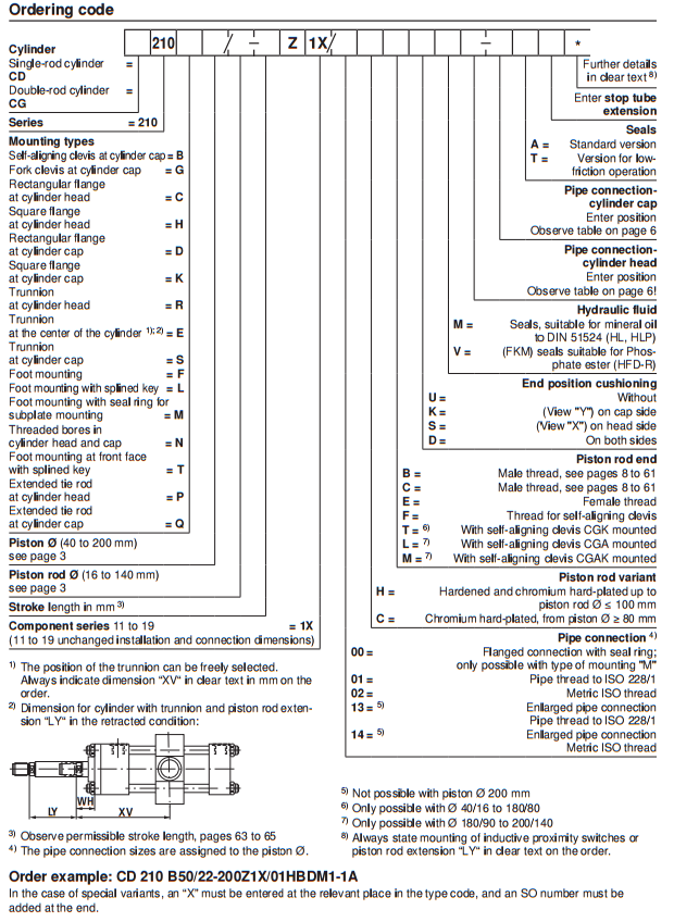
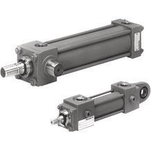
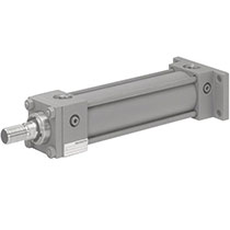
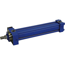
CD SERIES : REXROTH HYDRAULIC CYLIDER Tie Rod Cylinder

Rexroth Hydraulic Cylinder - Tie Rod Cylinder รุ่น CD Series กระบอกไฮดรอลิก แบบกระบอกสี่เสารั้ง สินค้าอุปกรณ์ไฮดรอลิกจาก Rexroth สินค้ามาตรฐานโลก ระดับสากล จัดจำหน่ายโดย นิวแอนด์ไฮด์ จำกัด ตัวแทนจำหน่ายอย่างเป็นทางการในประเทศไทยของ Rexroth (Rexroth Thailand)

  • Rexroth Tie Rod Cylinder รุ่น CD70

    รุ่น CD70

    1. Series 70
    2. Component series 1X
    3. Nominal pressure 70 bar
    4. Piston Ø 25 … 200 mm
    5. Piston rod Ø 12 … 140 mm
    6. Stroke length up to 3000 mm
  • Rexroth Tie Rod Cylinder รุ่น CD210

    รุ่น CD210

    1. Series H2
    2. Component series 3X
    3. Nominal pressure 250 bar
    4. Piston Ø 40 … 320 mm
    5. Piston rod Ø 25 … 220 mm
    6. Stroke length up to 6000 mm
  • Rexroth Tie Rod Cylinders รุ่น CDT3..Z-2X

    รุ่น CDT3...Z-2X

    1. Series T3
    2. Component series 3X
    3. Nominal pressure 160 bar
    4. Piston Ø 25 … 200 mm
    5. Piston rod Ø 12 … 140 mm
    6. Stroke length up to 3000 mm

Hydraulic cylinder รุ่น CD70

Tie Rod Cylinders : CD Series รุ่น CD70

CD CG CS
Hydraulic cylinder รุ่น CST3...Z-3X

รายละเอียด Hydraulic cylinder รุ่น CD70

  • Series 70
  • Component series 1X
  • Nominal pressure 70 bar
  • Piston Ø 25 … 200 mm
  • Piston rod Ø 12 … 140 mm
  • Stroke length up to 3000 mm

Features

  • 16 types of mounting

Type code

01020304 05 060708 091011121314 15161718
CD 70     /     Z 1X /                   *

01 Single rod cylinder CD
02 Series 70
Types of mounting
03 Spherical bearing at cylinder base B
Fork at cylinder base G 1)
Rectangular flange at cylinder head C 2)
Square flange at cylinder head H
Rectangular flange at cylinder base D 2)
Square flange at cylinder base K
Trunnion at cylinder head R 1)
Trunnion in cylinder center E 3)
Trunnion at cylinder base S
Foot mounting F
Foot mounting with fitting key L 2)
Foot mounting with seal ring sealing for subplate mounting M
Tapped holes in cylinder head and base N
Foot mounting on front side with fitting key T 1; 2)
Extended tie rod at cylinder head P
Extended tie rod at cylinder base Q
04 Piston Ø (ØAL) 25 … 200 mm ...
05 Piston rod Ø (ØMM) 12 … 140 mm ...
06 Stroke length in mm4) ...
Design principle
07 Cylinder head and cylinder base connected by tie rod Z
08 Component series 11 … 19 (11 … 19: unchanged installation and connection dimensions) 1X
Line connection / version
09 Flange connection with seal ring sealing; only possible with “M” type of mounting 00
Pipe thread according to ISO 228/1 01 10)
Metric ISO thread 02 10)
Enlarged line connection; pipe thread according to ISO 228/1 13 5; 10)
Enlarged line connection; metric ISO thread 14 5; 10)
Piston rod design
10 Hardened and hard chromium-plated H
Hard chromium-plated, from piston Ø ≥ 80 mm C 6)
Piston rod end
11 external thread B
external thread C
Internal thread E 7)
Thread for swivel head F
With mounted swivel head CGK T
End position cushioning
12 Without U
Base side K
Head side S
Both sides D
Hydraulic fluid
13 Seals, suitable for mineral oil according to DIN 51524 (HL, HLP) M
FKM seals suitable for phosphate ester (HFDR) V
Line connection/position at cylinder head
14 Enter position; observe the “position of the line connections” notices! View to piston rod8) CG70 symbol 01 1
2
3
4
Line connection/position at cylinder base
15 Enter position; observe the “position of the line connections” notices! View to piston rod8) CG70 symbol 02 1
2
3
4
Seals
16 Standard version A
Design for low-friction operation T
17 Enter support width extension
18 Further details in the plain text 9) *
  • 1) Not possible for piston Ø 25 mm0.98 in
  • 2) Not possible for piston Ø 200 mm7.87 in
  • 3) Position of trunnion freely selectable. When ordering, always specify the dimension "XV" in the plain text in mminch. With piston Ø 25 mm0.98 in, the trunnions are at the cylinder head.
  • 4) Observe the admissible stroke length, see “Admissible stroke lengths” in the project planning information.
  • 5) See dimensions. Not possible with type of mounting “K”.
  • 6) Not possible with piston rod end “E”.
  • 7) Not possible with piston rod Ø 12 mm0.47 in.
  • 8) All graphical representations in the data sheet show position 1.
  • 9) Always specify the attachment of inductive proximity switches or piston rod extensions “LY” in the order in the plain text.
  • 10) Not possible with type of mounting “M”.

Order example:
CD70B50/22-200Z1X/01HBDM1-1A
With special versions, an “X” will be inserted in the type key at the corresponding position and an SO number will be amended at the end.


Hydraulic cylinder รุ่น CD210

Hydraulic cylinder, tie rod design

CD210
Hydraulic cylinder รุ่น CD210

รายละเอียด Hydraulic cylinder รุ่น CD210

  • Series 210
  • Component series 1X
  • Nominal pressure 210 bar
  • Piston Ø 40 … 200 mm
  • Piston rod Ø 16 … 140 mm
  • Stroke length up to 3000 mm

Features

  • Service-friendly modular system
  • 16 types of mounting

Type code

cd210


Hydraulic cylinder รุ่น CDT3...Z-3X

Hydraulic cylinder tie rod design

CDT3 Z 3X
Hydraulic cylinder รุ่น CDT3...Z-3X

รายละเอียด Hydraulic cylinder รุ่น CDT3...Z-3X

  • Series T3
    (รุ่น T3)
  • Component series 3X
    (ใช่ร่วมกับรุ่น 3X)
  • Nominal pressure 160 bar
    (แรงดันปกติ 160 บาร์)
  • Piston Ø 25 … 200 mm
    (ขนาดลูกสูบ 25 - 200)
  • Piston rod Ø 12 … 140 mm
    (ก้านลูกสูบ 12 - 140)

Features

  • Installation dimension acc. to ISO 6020/2, DIN 24554 and NF/ISO 6020/2
    (ขนาดการติดตั้งมาตรฐาน ISO 6020/2, DIN 24554 และ NF/ISO 6020/2)
  • 13 types of mounting
    (มีการติดตั้ง 13 แบบ)
  • Integrated guide socket for fast and easy maintenance
    (เป็นแบบเต้ารับเพื่อรวดเร็วต่อการติดตั้งและซ่อมบำรุ่ง)
  • Optional self-adjusting or adjustable end position cushioning
    (ปรับกันกระแทกได้ด้วยตัวเองหรือตั่งค่าเองก็ได้)

SPECIFICATION (รายละเอียด)

แรงดันปกติbar160
แรงดันใช้งานขั้นต่ำ (ไม่มีภาระ) bar 10
แรงดันใช้งานสูงสุด (เมื่อมีภาระ) bar 210
แรงดันทดสอบเฉลี่ย bar 240
ลดแรงกดดันในการทดสอบ mm²/s 2,8 … 380
ความหนืดเหมาะสมที่อุณหภูมิใช้งาน mm²/s 20 … 100
ระดับการปนเปื้อนของน้ำมันไฮดรอลิกสูงสุดที่ยอมรับได้ระดับความสะอาดตาม ISO 4406 (c) Class 20/18/15 ตามมาตรฐาน ISO 4406 (c)
Bleeding By default

Type code

010203 04 05 06070809101112131415161718
CD T3   /   /   /   Z 3X                   *

01 Single rod cylinder CD
02 Series T3
Types of mounting
03 Types of mounting DIN/ISO Rectangular flange at cylinder head ME5
Rectangular flange at cylinder base ME6
Self-aligning clevis at cylinder base MP5
Foot mounting MS2
Trunnion in center MT4 1)
Types of mounting ISO Fork at cylinder base MP1
Swivel eye at cylinder base MP3
Trunnion at cylinder head MT1
Trunnion at cylinder base MT2
Extended tie rod, on both sides MX1
Extended tie rod at cylinder base MX2
Extended tie rod at cylinder head MX3
Tapped hole at cylinder head MX5 2)
04 Piston Ø (ØAL) 25 … 200 mm ...
05 Piston rod Ø (ØMM) 12 … 140 mm13) ...
06 Stroke length in mm11) ...
Design principle
07 Cylinder head and cylinder base connected by tie rod Z
Component series
08 Component series 30 … 39 (30 … 39: unchanged installation and connection dimensions) 3X
Line connection / version
09 Pipe thread according to ISO 1179-1 B
Metric ISO thread (ISO 6149-1) R 17)
Enlarged pipe thread (ISO 1179-1) S
Line connection/position at cylinder head
10 View to piston rod CST3 Z 3X symbol 01 1
2
3
4
Line connection/position at cylinder base
11 View to piston rod
CST3 Z 3X symbol 02
1
2
3
4
Piston rod design
12 Hardened and hard chromium-plated H
Piston rod end
13 Thread (DIN/ISO) for swivel head CGKA H 14)
Thread (ISO) for swivel head CGKA D 15)
Internal thread E 12)
With mounted swivel head CGKA (DIN/ISO) F 5; 14)
With mounted swivel head CGKA (ISO) K 5; 15)
With trunnion T 6)
End position cushioning
14 Without end position cushioning U
Both sides, self-adjusting D
Head sides, self-adjusting S
Base sides, self-adjusting K
Both sides, adjustable E 4)
Seal design
15 Standard seal system M
Reduced friction T
High temperature with reduced friction S
Option 1
16 Without option W
Leakage oil connection B 3; 4; 16)
Threaded coupling, on both sides A
Option 2
17 Without option W
Piston rod extension “LY”, specify in mmin plain text Y
18 Further details in the plain text ...
  • 1) Trunnion position freely selectable. When ordering, always specify the "XV" dimensions in the plain text in mm
  • 2) Not ISO-standardized
  • 3) For type of mounting MS2 and piston Ø 25 mm and end position cushioning “E” not possible
  • 4) With piston Ø 25 … 100 mm: only line connection “B” possible.
    With piston Ø 125 … 200 mm: only DIN type of mounting and line connection “B” possible.
  • 5) Not possible with type of mounting Mx1 and MX3
  • 6) See dimensions - piston rod ends E and T (only possible with standardized piston rod Ø 22 … 140 mm, observe max. operating pressure.
  • 11) For max. available stroke length, see technical data, and for admissible stroke length (according to the kinking calculation), see project planning information.
  • 12) See dimensions - piston rod ends E and T (only possible with standardized piston rod Ø 18 … 140 mm, observe max. operating pressure.
  • 13) Observe the admissible piston rod Ø and assigned threads at the piston rod end for 210 bar (see technical data and dimensions)
  • 14) For operating pressure up to 160 bar
  • 15) For operating pressure up to 210 bar
  • 16) Not possible with MT1
  • 17) For type of mounting ME5 and ME6, only position 1 and 3 possible

Order examples:
CDT3MP5/50/36/300Z3X/B11HHDMWW
Please observe the relevant restrictions when selecting!


ติดต่อ Rexroth / งานโปรเจ็ค / กระบอกไฮดรอลิก / งานซ่อม และงานบริการ

Rexroth contact
ดาว์นโหลด แคตตาล็อก, สเป้กแอร์แทค
Promotion-Big Sale
ติดต่อเรา
TICTechnology Instrument 
www.tic.co.th
tupackT.U Pack 
www.tupack.co.th
Your LiftYour Lift 
www.yourlift.co.th