
OMRON Basic Switches - X
Basic Switches - X
Download PDF
Model Numbers | Basic Switches - X
| Terminal | Solder terminal  | Screw terminal  | |
|---|---|---|---|
| Actuator | Model | Model | |
| Pin plunger |  |
X-10G | X-10G-B |
| Slim spring plunger |  |
X-10GS | X-10GS-B |
| Short spring plunger |  |
X-10GD | X-10GD-B |
| Panel mount plunger |  |
X-10GQ | X-10GQ-B |
| Panel mount roller plunger |  |
X-10GQ22 | X-10GQ22-B |
| Panel mount cross roller plunger |  |
X-10GQ21 | X-10GQ21-B |
| Leaf spring |  |
X-10GL | X-10GL-B |
| Short hinge lever |  |
X-10GW21 | X-10GW21-B |
| Hinge lever |  |
X-10GW | X-10GW-B |
| Low-force hinge lever |  |
X-10GW4 | X-10GW4-B |
| Short hinge roller lever |  |
X-10GW22 | X-10GW22-B |
| Hinge roller lever B |  |
X-10GW2 | X-10GW2-B |
| Reverse hinge lever |  |
X-10GM | X-10GM-B |
| Reverse short hinge roller lever * |  |
X-10GM22 | X-10GM22-B |
| Reverse hinge roller lever * |  |
X-10GM2 | X-10GM2-B |
* The plungers of reverse-type models are continuously pressed by the compression coil springs and the plungers are
freed by operating the levers.
Accessories (Order Separately)
Terminal Covers (Sold Separately)
The Terminal Covers can be attached to Z, A, X, and DZ Switches.
The Terminal Cover is secured with mounting screws and protects the casing and terminal wires from dust, vibration, or fingers, thus preventing terminal short-circuiting, ground faults, wire disconnection or improper connection, and electric shock accidents.
Terminal Covers made of phenol resin have five or six thin wall sections. These sections can be torn open for providing holes for lead cables at desired points.
A terminal cover can’t be used in the case of using an actuator sold separately.
| Application | Soldering terminal use | Screw terminal use | Remarks | |
|---|---|---|---|---|
| Material | Mounting direction | Model | ||
| Phenol resin | Side mounting | AP-A | AP-B | --- |
| Metal press mold | Side mounting | AP1-A | AP1-B | Used for AP-A and AP-B |
| Vinyl chloride | Side mounting | AP-Z | --- | |
Note: Use a Terminal Cover for screw terminals fir DZ-series Switches with soldering terminals.
Separator (Sold Separately)
Use a Separator when it is difficult to provide a sufficient insulation distance or when using the Switch near metal parts or copper wires.
| Model |
|---|
| SEPARATOR FOR Z |
Actuators (Sold Separately)
A Switch can be actuated by a cam or an appropriate object, in which case, use one of the following Actuators according to the application.
| Actuator | Common to Z and X models | ||
|---|---|---|---|
| Hinge lever |  |
XAA-1 | |
| Hinge roller lever |  |
ZAA-2 | |
| Panel mount plunger |  | Short | ZAQ-3 |
| Medium | ZAQ-2 | ||
| Long | ZAQ-1 | ||
| Panel mount roller plunger |  |
ZAQ-22 | |
Specifications | Basic Switches - X
Ratings
| Rated voltage | Non-inductive load (A) | Inductive load (A) | ||||||
|---|---|---|---|---|---|---|---|---|
| Resistive load | Lamp load | Inductive load | Motor load | |||||
| NC | NO | NC | NO | NC | NO | NC | NO | |
| 8 VDC 14 VDC 30 VDC 125 VDC 250 VDC |
10 10 10 10 3 |
3 3 3 3 1.5 |
1.5 1.5 1.5 1.5 0.75 |
10 10 10 7.5 2 |
10 10 10 6 1.5 |
5 5 5 5 2 |
2.5 2.5 2.5 2.5 1.5 |
|
Note:Note:
1. The above values are for the steady-state current.
2. Inductive load has a power factor of 0.4 min. (AC) and a time constant of 7 ms max. (DC).
3. Lamp load has an inrush current of 10 times the steady-state current.
4. Motor load has an inrush current of 6 times the steady-state current.
5. The above electrical ratings also apply to the AC voltage.
6. With the reverse-type models (X-10GM[]), the normally closed circuits and normally open circuits are reversed.
7. The ratings values apply under the following test conditions:
(1) Ambient temperature: 20±2℃
(2) Ambient humidity: 65±5%RH
(3) Operating frequency: 20 operations/min
Contact Specification
| Contacts | Material | Silver |
|---|---|---|
| Gap (standard value) | 0.9 mm | |
| Inrush current | NC | 30 A max. |
| NO | 15 A max. |
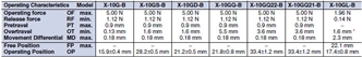
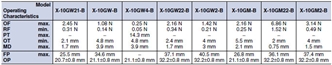
Characteristics
| Operating speed | 0.1 mm to 1 m/s *1 | |
|---|---|---|
| Operating frequency | Mechanical | 240 operations/min |
| Electrical | 20 operations/min | |
| Insulation resistance | 100 M Ω min. (at 500 VDC) | |
| Contact resistance | 15 m Ω max. (initial value) | |
| Dielectric strength | 1,500 VAC, 50/60 Hz for 1 min between terminals of the same polarity, between current-carrying metal parts and the ground, and between each terminal and non-current-carrying metal parts | |
| Vibration resistance | Malfunction | 10 to 55 Hz, 1.5-mm double amplitude *2 |
| Shock resistance | Destruction | 1,000 m/s2 max. |
| Malfunction | 300 m/s2 max. *1 *2 | |
| Durability | Mechanical | 1,000,000 operations min. |
| Electrical | 100,000 operations min. | |
| Degree of protection | IP00 | |
| Degree of protection against electric shock |
Class I | |
| Proof tracking index (PTI) | 175 | |
| Ambient operating temperature | − 25 ° C to 80 ° C (with no icing) | |
| Ambient operating humidity | 35% to 85%RH | |
| Weight | Approx. 27 to 63 g | |
Note:*1. The values are for the pin plunger models. (Contact your OMRON representative for other models.)
*2. Malfunction: 1 ms max.
Dimensions | Basic Switches - X
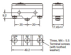
Terminals
Screw Terminals (-B)
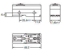
Solder Terminal (-A)
("-A" is not included in the model numbers.)
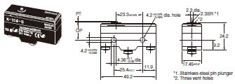
Note: 1. Tighten the terminal screws to a torque of 0.78 to 1.18 Nm.
2. Unless otherwise specified, a tolerance of ±0.4 mm applies to all dimensions.
3. In case of DC voltage, set the COM to the positive terminal.
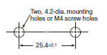
Mounting
Use M4 mounting screws with plane washers or spring washers to securely mount the Switch. Tighten the screws to a torque of 1.18 to 1.47 Nm.
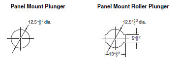
The Switch can be panel mounted, provided that the hexagonal nut of the actuator is tightened to a torque of 2.94 to 4.9 Nm.
The models, illustrations, and graphics are for screw-terminal models. (The dimensions for models that are omitted here are the same as for pin-plunger models.)
Pin Plunger
X-10G-B
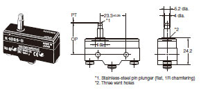
Slim Spring Plunger
X-10GS-B
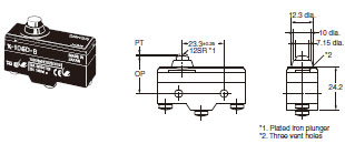
Short Spring Plunger
X-10GD-B
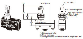
Panel Mount Plunger
X-10GQ-B
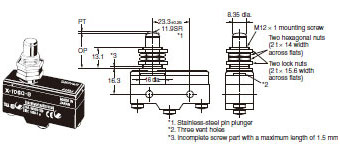
Note: Do not use both the M12 mounting screw and the mounting holes in the case at the same time. Doing so will cause
stress to be applied to the Switch, possibly damaging the case or cover.
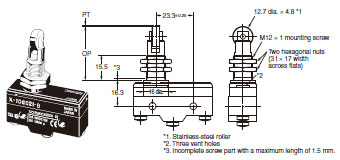
Panel Mount Roller Plunger
X-10GQ22-B
Note: Do not use both the M12 mounting screw and the mounting holes in the case at the same time. Doing so will cause
stress to be applied to the Switch, possibly damaging the case or cover.
Panel Mount Cross Roller Plunger
X-10GQ21-B
Note: Do not use both the M12 mounting screw and the mounting holes in the case at the same time. Doing so will cause
stress to be applied to the Switch, possibly damaging the case or cover.
Leaf Spring
X-10GL-B
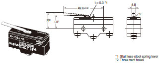
Note: Unless otherwise specified, a tolerance of ±0.4 mm applies to all dimensions.
* Be sure to use the switch at the rated OT value of 1.6 mm.
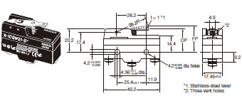
Short Hinge Lever
X-10GW21-B
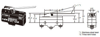
Hinge Lever
X-10GW-B
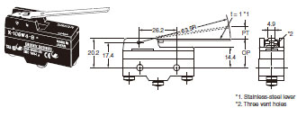
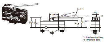
Low-force Hinge Lever
X-10GW4-B
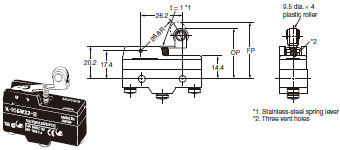
Short Hinge Roller Lever
X-10GW22-B
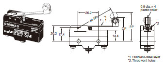
Hinge Roller Lever
X-10GW2-B
Reverse Hinge Lever
X-10GM-B
Reverse Short Hinge Lever
X-10GM22-B
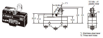
Reverse Hinge Roller Lever
X-10GM2-B
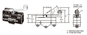
Note: Unless otherwise specified, a tolerance of ±0.4 mm applies to all dimensions.
Terminal Covers
AP-A
Soldering Terminal Use (Phenol Resin)
Note: The Cover has five thin, easy-to-separate portions for easy lead wire connections.
AP-B
Screw Terminal Use (Phenol Resin)
Note: The Cover has six thin, easy-to-separate portions for easy lead wire connections.
AP1-A
Soldering Terminal Use (Metal Press Mold)
Note: The Cover has five holes for easy lead wire connections.
AP1-B
Screw Terminal Use (Metal Press Mold)
Note: The Cover has six holes for easy lead wire connections.
AP-Z
Soldering or Screw Terminal Use (Vinyl Chloride)
Note: Each dimension has a tolerance of ±0.4 mm unless otherwise specified. (±0.8 mm for the AP-Z)
Separator
SEPARATOR FOR Z
Note: 1. Each dimension has a tolerance of ±0.4 mm unless otherwise specified.
2. The material is EAVTC (Epoxide Alkyd Varnished Tetron Cloth) and its heat-resisting temperature is 130°C.
Actuators
Hinge Lever
XAA-1
Hinge Roller Lever
ZAA-2
Short Panel Mount Plunger
ZAQ-3
Medium Panel Mount Plunger
ZAQ-2
Long Panel Mount Plunger
ZAQ-1
Panel Mount Roller Plunger
ZAQ-22
Note: Each dimension has a tolerance of ±0.4 mm unless otherwise specified.
Features | Basic Switches - X
Incorporates a small permanent magnet in the contact mechanism to deflect the arc to effectively extinguish it.
Properties | Basic Switches - X
| Basic Switches | X |
|---|---|
| Rated voltage | 8 - 250 VDC |
| Service life | 1,000,000 times |
| Contact distance | 0.9 mm (default) |
| Contact resistance | 15 mΩ min (default) |
| Insulation resistance | 100 MΩ min (500 VDC) |
| Weight (g) | Approx 27 - 63 |
Basic Switches - X
ดาวน์โหลดไฟล์ PDF คุณสมบัติ | Basic Switches - X
X เป็นเบสิกสวิตซ์ (Basic Switch) ที่ทนอุณหภูมิสูง สำหรับการสลับโหลดไฟฟ้าแรงสูง ไฟฟ้ากระแสตรง DC และวงจรคู่
ข้อมูลจำเพาะ | Basic Switches - X
| Basic Switches | X |
|---|---|
| พิกัดแรงดัน | 8 - 250 VDC |
| อายุการใช้งาน | 1,000,000 ครั้ง |
| ระยะห่างหน้าสัมผัส | 0.9 mm (ค่ามาตรฐาน) |
| ความต้านทานหน้าสัมผัส | 15 mΩ min (ค่าเริ่มต้น) |
| ความต้านทานของฉนวน | 100 MΩ min (ที่ 500 VDC) |
| น้ำหนัก | ประมาณ 27 - 63 กรัม |


 Your Lift