
OMRON Proximity Sensor - E2E
Proximity Sensor Cylindrical - E2E
Download PDF
Model Numbers | Proximity Sensor Cylindrical - E2E
2-Wire Models
Shielded DC 2-wire Models with No Self-diagnostic Output
| Appearance | Sensing distance | Connection method | Cable specifications | Polarity | Operation mode | Pin arrangement | Applicable connector code *2 | Model |
|---|---|---|---|---|---|---|---|---|
| M8 | 2 mm | M12 Pre- wired Smartclick Connector Models (0.3 m) |
PUR (increased oil-resistant) |
Yes | NO | 1: +V, 4: 0 V |
H | E2E-X2D1-M1TGJ-U 0.3M |
| NC | 1: +V, 2: 0 V |
E2E-X2D2-M1TGJ-U 0.3M | ||||||
| PVC (oil-resistant) |
NO | 1: +V, 4: 0 V |
G | E2E-X2D1-M1TGJ 0.3M | ||||
| Pre-wired Models (2 m) |
PUR (increased oil-resistant) |
NO | --- | --- | E2E-X2D1-U 2M | |||
| NC | E2E-X2D2-U 2M | |||||||
| PVC (oil-resistant) |
NO | E2E-X2D1-N 2M | ||||||
| NC | E2E-X2D2-N 2M | |||||||
| M12 Connector Models |
--- | NO | 1: +V, 4: 0 V |
A | E2E-X2D1-M1G | |||
| NC | 1: +V, 2: 0 V |
D | E2E-X2D2-M1G | |||||
| M8 Connector Models |
--- | NO | 1: +V, 4: 0 V |
I | E2E-X2D1-M3G | |||
| NC | 1: +V, 2: 0 V |
E2E-X2D2-M3G | ||||||
| M12 | 3 mm | M12 Pre- wired Smartclick Connector Models (0.3 m) |
PUR (increased oil-resistant) |
Yes | NO | 1: +V, 4: 0 V |
H | E2E-X3D1-M1TGJ-U 0.3M |
| NC | 1: +V, 2: 0 V |
E2E-X3D2-M1TGJ-U 0.3M | ||||||
| PVC (oil-resistant) |
NO | 1: +V, 4: 0 V |
G | E2E-X3D1-M1TGJ 0.3M | ||||
| Pre-wired Models (2 m) |
PUR (increased oil-resistant) |
NO | --- | --- | E2E-X3D1-U 2M | |||
| NC | E2E-X3D2-U 2M | |||||||
| PVC (oil-resistant) |
NO | E2E-X3D1-N 2M *1 | ||||||
| NC | E2E-X3D2-N 2M | |||||||
| M12 Connector Models |
--- | NO | 1: +V, 4: 0 V |
A | E2E-X3D1-M1G *1 | |||
| NC | 1: +V, 2: 0 V |
D | E2E-X3D2-M1G | |||||
| M12 Standard Pre-wired Connector Models (0.3 m) |
PVC (oil-resistant) |
Yes | NO | 1: +V, 4: 0 V |
A | E2E-X3D1-M1GJ 0.3M | ||
| NC | 1: +V, 2: 0 V |
D | E2E-X3D2-M1GJ 0.3M | |||||
| No *3 | NO | (3, 4): (+V, 0 V) |
C | E2E-X3D1-M1J-T 0.3M | ||||
| NC | (1, 2): (+V, 0 V) |
D | --- | |||||
| M18 | 7 mm | M12 Pre- wired Smartclick Connector Models (0.3 m) |
PUR (increased oil-resistant) |
Yes | NO | 1: +V, 4: 0 V |
H | E2E-X7D1-M1TGJ-U 0.3M |
| NC | 1: +V, 2: 0 V |
E2E-X7D2-M1TGJ-U 0.3M | ||||||
| PVC (oil-resistant) |
NO | 1: +V, 4: 0 V |
G | E2E-X7D1-M1TGJ 0.3M | ||||
| Pre-wired Models (2 m) |
PUR (increased oil-resistant) |
NO | --- | --- | E2E-X7D1-U 2M | |||
| NC | E2E-X7D2-U 2M | |||||||
| PVC (oil-resistant) |
NO | E2E-X7D1-N 2M *1 | ||||||
| NC | E2E-X7D2-N 2M | |||||||
| M12 Connector Models |
--- | NO | 1: +V, 4: 0 V |
A | E2E-X7D1-M1G *1 | |||
| NC | 1: +V, 2: 0 V |
D | E2E-X7D2-M1G | |||||
| M12 Standard Pre-wired Connector Models (0.3 m) |
PVC (oil-resistant) |
Yes | NO | 1: +V, 4: 0 V |
A | E2E-X7D1-M1GJ 0.3M | ||
| NC | 1: +V, 2: 0 V |
D | E2E-X7D2-M1GJ 0.3M | |||||
| No *3 | NO | (3, 4): (+V, 0 V) |
C | E2E-X7D1-M1J-T 0.3M | ||||
| NC | (1, 2): (+V, 0 V) |
D | E2E-X7D2-M1J-T 0.3M | |||||
| M30 | 10 mm | M12 Pre- wired Smartclick Connector Models (0.3 m) |
PUR (increased oil-resistant) |
Yes | NO | 1: +V, 4: 0 V |
H | E2E-X10D1-M1TGJ-U 0.3M |
| NC | 1: +V, 2: 0 V |
E2E-X10D2-M1TGJ-U 0.3M | ||||||
| PVC (oil-resistant) |
NO | 1: +V, 4: 0 V |
G | E2E-X10D1-M1TGJ 0.3M | ||||
| Pre-wired Models (2 m) |
PUR (increased oil-resistant) |
NO | --- | --- | E2E-X10D1-U 2M | |||
| NC | E2E-X10D2-U 2M | |||||||
| PVC (oil-resistant) |
NO | E2E-X10D1-N 2M *1 | ||||||
| NC | E2E-X10D2-N 2M | |||||||
| M12 Connector Models |
--- | NO | 1: +V, 4: 0 V |
A | E2E-X10D1-M1G *1 | |||
| NC | 1: +V, 2: 0 V |
D | E2E-X10D2-M1G | |||||
| M12 Standard Pre-wired Connector Models (0.3 m) |
PVC (oil-resistant) |
Yes | NO | 1: +V, 4: 0 V |
A | E2E-X10D1-M1GJ 0.3M | ||
| PVC (oil-resistant) |
NC | 1: +V, 2: 0 V |
D | E2E-X10D2-M1GJ 0.3M | ||||
| PVC (oil-resistant) |
No *3 | NO | (3, 4): (+V, 0 V) |
C | E2E-X10D1-M1J-T 0.3M | |||
| PVC (oil-resistant) |
NC | (1, 2): (+V, 0 V) |
D | E2E-X10D2-M1J-T 0.3M |
*1. Models with different frequencies are also available. The model number is E2E-X[]D15 (example: E2E-X3D15-N 2M).
*2. Refer to Data Sheet for details.
*3. The residual voltage for models without polarity is 5 V, so use caution concerning the connection load interface
conditions (e.g., PLC ON voltage).
Refer to Data Sheet.
Shielded DC 2-Wire UL-recognized Models with No Self-diagnostic Output
| Appearance | Sensing distance | Connection method | Cable specifications | Polarity | Operation mode | Pin arrangement | Applicable connector code * | Model |
|---|---|---|---|---|---|---|---|---|
| M8 | 2 mm | M12 Pre-wired Smartclick Connector Models (0.3 m) |
PVC (oil- resistant) |
Yes | NO | 1: +V, 4: 0 V |
G | E2E-X2D1-M1TGJ-US 0.3M |
| NC | 1: +V, 2: 0 V |
E2E-X2D2-M1TGJ-US 0.3M | ||||||
| Pre-wired Models (2 m) |
NO | --- | --- | E2E-X2D1-US 2M | ||||
| NC | E2E-X2D2-US 2M | |||||||
| M12 | 3 mm | M12 Pre-wired Smartclick Connector Models (0.3 m) |
NO | 1: +V, 4: 0 V |
G | E2E-X3D1-M1TGJ-US 0.3M | ||
| NC | 1: +V, 2: 0 V |
E2E-X3D2-M1TGJ-US 0.3M | ||||||
| Pre-wired Models (2 m) |
NO | --- | --- | E2E-X3D1-US 2M | ||||
| NC | E2E-X3D2-US 2M | |||||||
| M18 | 7 mm | M12 Pre-wired Smartclick Connector Models (0.3 m) |
NO | 1: +V, 4: 0 V |
G | E2E-X7D1-M1TGJ-US 0.3M | ||
| NC | 1: +V, 2: 0 V |
E2E-X7D2-M1TGJ-US 0.3M | ||||||
| Pre-wired Models (2 m) |
NO | --- | --- | E2E-X7D1-US 2M | ||||
| NC | E2E-X7D2-US 2M | |||||||
| M30 | 10 mm | M12 Pre-wired Smartclick Connector Models (0.3 m) |
NO | 1: +V, 4: 0 V |
G | E2E-X10D1-M1TGJ-US 0.3M | ||
| NC | 1: +V, 2: 0 V |
E2E-X10D2-M1TGJ-US 0.3M | ||||||
| Pre-wired Models (2 m) |
NO | --- | --- | E2E-X10D1-US 2M | ||||
| NC | E2E-X10D2-US 2M |
* Refer to Data Sheet for details.
Unshielded DC 2-Wire Models with No Self-diagnosis Output
| Appearance | Sensing distance | Connection method | Cable specifications | Polarity | Operation mode | Pin arrangement | Applicable connector code *2 | Model |
|---|---|---|---|---|---|---|---|---|
| M8 | 4 mm | Pre-wired Models (2 m) |
PVC (oil-resistant) |
Yes | NO | --- | --- | E2E-X4MD1 2M |
| NC | E2E-X4MD2 2M | |||||||
| M12 Connector Models |
--- | NO | 1: +V, 4: 0 V |
A | E2E-X4MD1-M1G | |||
| NC | 1: +V, 2: 0 V |
D | E2E-X4MD2-M1G | |||||
| M8 Connector Models |
--- | NO | 1: +V, 4: 0 V |
I | E2E-X4MD1-M3G | |||
| NC | 1: +V, 2: 0 V |
E2E-X4MD2-M3G | ||||||
| M12 | 8 mm | M12 Pre-wired Smartclick Connector Models (0.3 m) |
PVC (oil-resistant) |
NO | 1: +V, 4: 0 V |
G | E2E-X8MD1-M1TGJ 0.3M | |
| Pre-wired Models (2 m) |
PVC (oil-resistant) |
NO | --- | --- | E2E-X8MD1 2M *1 | |||
| NC | E2E-X8MD2 2M | |||||||
| M12 Connector Models |
--- | NO | 1: +V, 4: 0 V |
A | E2E-X8MD1-M1G *1 | |||
| NC | 1: +V, 2: 0 V |
D | E2E-X8MD2-M1G | |||||
| M12 Standard Pre-wired Connector Models (0.3 m) |
PVC (oil-resistant) |
NO | 1: +V, 4: 0 V |
A | E2E-X8MD1-M1GJ 0.3M | |||
| NC | 1: +V, 2: 0 V |
D | --- | |||||
| M18 | 14 mm | M12 Pre-wired Smartclick Connector Models (0.3 m) |
PVC (oil-resistant) |
NO | 1: +V, 4: 0 V |
G | E2E-X14MD1-M1TGJ 0.3M | |
| Pre-wired Models (2 m) |
PVC (oil-resistant) |
NO | --- | --- | E2E-X14MD1 2M *1 | |||
| NC | E2E-X14MD2 2M | |||||||
| M12 Connector Models |
--- | NO | 1: +V, 4: 0 V |
A | E2E-X14MD1-M1G *1 | |||
| NC | 1: +V, 2: 0 V |
D | E2E-X14MD2-M1G | |||||
| M12 Standard Pre-wired Connector Models (0.3 m) |
PVC (oil-resistant) |
NO | 1: +V, 4: 0 V |
A | E2E-X14MD1-M1GJ 0.3M | |||
| NC | 1: +V, 2: 0 V |
D | E2E-X14MD2-M1GJ 0.3M | |||||
| M30 | 20 mm | M12 Pre-wired Smartclick Connector Models (0.3 m) |
PVC (oil-resistant) |
NO | 1: +V, 4: 0 V |
G | E2E-X20MD1-M1TGJ 0.3M | |
| Pre-wired Models (2 m) |
PVC (oil-resistant) |
NO | --- | --- | E2E-X20MD1 2M *1 | |||
| NC | E2E-X20MD2 2M | |||||||
| M12 Connector Models |
--- | NO | 1: +V, 4: 0 V |
A | E2E-X20MD1-M1G *1 | |||
| NC | 1: +V, 2: 0 V |
D | E2E-X20MD2-M1G | |||||
| M12 Standard Pre-wired Connector Models (0.3 m) |
PVC (oil-resistant) |
NO | 1: +V, 4: 0 V |
A | E2E-X20MD1-M1GJ 0.3M | |||
| NC | 1: +V, 2: 0 V |
D | --- |
*1. Models with different frequencies are also available. The model number is E2E-X[]D15 (example: E2E-X8MD15 2M).
*2. Refer to Data Sheet for details.
Unshielded DC 2-Wire UL-recognized Models with No Self-diagnostic Output
| Appearance | Sensing distance | Connection method | Cable specifications | Polarity | Operation mode | Pin arrangement | Applicable connector code * | Model |
|---|---|---|---|---|---|---|---|---|
| M8 | 4 mm | M12 Pre-wired Smartclick Connector Models (0.3 m) |
PVC (oil- resistant) |
Yes | NO | 1: +V, 4: 0 V |
G | E2E-X4MD1-M1TGJ-US 0.3M |
| NC | 1: +V, 2: 0 V |
E2E-X4MD2-M1TGJ-US 0.3M | ||||||
| Pre-wired Models (2 m) |
NO | --- | --- | E2E-X4MD1-US 2M | ||||
| NC | E2E-X4MD2-US 2M | |||||||
| M12 | 8 mm | M12 Pre-wired Smartclick Connector Models (0.3 m) |
NO | 1: +V, 4: 0 V |
G | E2E-X8MD1-M1TGJ-US 0.3M | ||
| NC | 1: +V, 2: 0 V |
E2E-X8MD2-M1TGJ-US 0.3M | ||||||
| Pre-wired Models (2 m) |
NO | --- | --- | E2E-X8MD1-US 2M | ||||
| NC | E2E-X8MD2-US 2M | |||||||
| M18 | 14 mm | M12 Pre-wired Smartclick Connector Models (0.3 m) |
NO | 1: +V, 4: 0 V |
G | E2E-X14MD1-M1TGJ-US 0.3M | ||
| NC | 1: +V, 2: 0 V |
E2E-X14MD2-M1TGJ-US 0.3M | ||||||
| Pre-wired Models (2 m) |
NO | --- | --- | E2E-X14MD1-US 2M | ||||
| NC | E2E-X14MD2-US 2M | |||||||
| M30 | 20 mm | M12 Pre-wired Smartclick Connector Models (0.3 m) |
NO | 1: +V, 4: 0 V |
G | E2E-X20MD1-M1TGJ-US 0.3M | ||
| NC | 1: +V, 2: 0 V |
E2E-X20MD2-M1TGJ-US 0.3M | ||||||
| Pre-wired Models (2 m) |
NO | --- | --- | E2E-X20MD1-US 2M | ||||
| NC | E2E-X20MD2-US 2M |
* Refer to Data Sheet for details.
Shielded DC 2-Wire Models with Self-diagnosis Output
| Appearance | Sensing distance | Connection method | Cable specifications | Polarity | Operation mode | Pin arrangement | Applicable connector code *2 | Model |
|---|---|---|---|---|---|---|---|---|
| M12 | 3 mm | Pre-wired Models (2 m) |
PVC (oil- resistant) |
Yes | NO | --- | --- | E2E-X3D1S 2M *1 |
| M12 Connector Models |
--- | 2: +V and diagnostic output 3: 0 V 4: +V and control output |
D | E2E-X3D1S-M1 | ||||
| M18 | 7 mm | Pre-wired Models (2 m) |
PVC (oil- resistant) |
--- | --- | E2E-X7D1S 2M *1 | ||
| M12 Connector Models |
--- | 2: +V and diagnostic output 3: 0 V 4: +V and control output |
D | E2E-X7D1S-M1 | ||||
| M30 | 10 mm | Pre-wired Models (2 m) |
PVC (oil- resistant) |
--- | --- | E2E-X10D1S 2M *1 | ||
| M12 Connector Models |
--- | 2: +V and diagnostic output 3: 0 V 4: +V and control output |
D | E2E-X10D1S-M1 |
*1. Models with different frequencies are also available. The model number is E2E-X[]D15S (example: E2E-X3D15S 2M).
*2. Refer to Data Sheet for details.
Unshielded DC 2-Wire Models with Self-diagnosis Output
| Appearance | Sensing distance | Connection method | Cable specifications | Polarity | Operation mode | Pin arrangement | Applicable connector code *2 | Model |
|---|---|---|---|---|---|---|---|---|
| M12 | 8 mm | Pre-wired Models (2 m) |
PVC (oil- resistant) |
Yes | NO | --- | --- | E2E-X8MD1S 2M *1 |
| M12 Connector Models |
--- | 2: +V and diagnostic output 3: 0 V 4: +V and control output |
D | E2E-X8MD1S-M1 | ||||
| M18 | 14 mm | Pre-wired Models (2 m) |
PVC (oil- resistant) |
--- | --- | E2E-X14MD1S 2M *1 | ||
| M12 Connector Models |
--- | 2: +V and diagnostic output 3: 0 V 4: +V and control output |
D | E2E-X14MD1S-M1 | ||||
| M30 | 20 mm | Pre-wired Models (2 m) |
PVC (oil- resistant) |
--- | --- | E2E-X20MD1S 2M *1 | ||
| M12 Connector Models |
--- | 2: +V and diagnostic output 3: 0 V 4: +V and control output |
D | E2E-X20MD1S-M1 |
*1. Models with different frequencies are also available. The model number is E2E-X[]MD15S (example: E2E-X8MD15S 2M).
*2. Refer to Data Sheet for details.
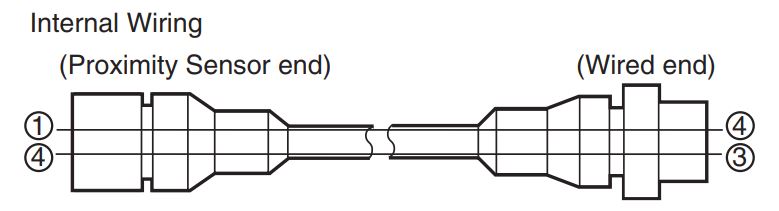
Connector Pin Assignments of DC 2-Wire Models
• The connector pin assignments of each New E2E DC 2-Wire Model conform to IEC 947-5-2 Table III. (Only DC 2-Wire Models have been changed in comparison to the previous models.)
• The following models with conventional connector pin assignments are available as well. (Only NO Models can be used.) The cable at the right should also be used if the XW3D-P[]55-G11/XW3B-P[]55-G11 Connector Junction Box is already being used.
| Cable length | Model |
|---|---|
| 500 mm | XS2W-D421-BY1 |
Models with conventional connector pin assignments are available as well.
| Appearance | Model | ||||
|---|---|---|---|---|---|
| NO | Applicable connector code * | NC | Applicable connector code * | ||
 |
M8 | E2E-X2D1-M1 | C | E2E-X2D2-M1 | D |
| M12 | E2E-X3D1-M1 | C | E2E-X3D2-M1 | D | |
| M18 | E2E-X7D1-M1 | C | E2E-X7D2-M1 | D | |
| M30 | E2E-X10D1-M1 | C | E2E-X10D2-M1 | D | |
 |
M8 | E2E-X4MD1-M1 | C | E2E-X4MD2-M1 | D |
| M12 | E2E-X8MD1-M1 | C | E2E-X8MD2-M1 | D | |
| M18 | E2E-X14MD1-M1 | C | E2E-X14MD2-M1 | D | |
| M30 | E2E-X20MD1-M1 | C | E2E-X20MD2-M1 | D | |
* Refer to Data Sheet for details.
AC 2-Wire Models Shielded Models
| Appearance | Sensing distance | Connection method | Cable specifications | Operation mode | Pin arrangement | Applicable connector code *2 | Model |
|---|---|---|---|---|---|---|---|
| M8 | 1.5 mm | Pre-wired Models (2 m) |
PVC (oil-resistant) |
NO | --- | --- | E2E-X1R5Y1 2M |
| NC | E2E-X1R5Y2 2M | ||||||
| M12 | 2 mm | Pre-wired Models (2 m) |
PVC (oil-resistant) |
NO | --- | --- | E2E-X2Y1 2M *1 |
| NC | E2E-X2Y2 2M | ||||||
| M12 Connector Models |
--- | NO | (3, 4): (AC, AC) | E | E2E-X2Y1-M1 | ||
| NC | (1, 2): (AC, AC) | F | E2E-X2Y2-M1 | ||||
| M18 | 5 mm | Pre-wired Models (2 m) |
PVC (oil-resistant) |
NO | --- | --- | E2E-X5Y1 2M *1 |
| NC | E2E-X5Y2 2M | ||||||
| M12 Connector Models |
--- | NO | (3, 4): (AC, AC) | E | E2E-X5Y1-M1 | ||
| NC | (1, 2): (AC, AC) | F | E2E-X5Y2-M1 | ||||
| M30 | 10 mm | Pre-wired Models (2 m) |
PVC (oil-resistant) |
NO | --- | --- | E2E-X10Y1 2M *1 |
| NC | E2E-X10Y2 2M | ||||||
| M12 Connector Models |
--- | NO | (3, 4): (AC, AC) | E | E2E-X10Y1-M1 | ||
| NC | (1, 2): (AC, AC) | F | E2E-X10Y2-M1 |
*1. Models with different frequencies are also available. The model number is E2E-X[]Y[]5 (example: E2E-X5Y15 2M).
*2. Refer to Data Sheet for details.
Unshielded Models
| Appearance | Sensing distance | Connection method | Cable specifications | Operation mode | Pin arrangement | Applicable connector code *2 | Model |
|---|---|---|---|---|---|---|---|
| M8 | 2 mm | Pre-wired Models (2 m) |
PVC (oil-resistant) |
NO | --- | --- | E2E-X2MY1 2M |
| NC | E2E-X2MY2 2M | ||||||
| M12 | 5 mm | Pre-wired Models (2 m) |
PVC (oil-resistant) |
NO | --- | --- | E2E-X5MY1 2M *1 |
| NC | E2E-X5MY2 2M | ||||||
| M12 Connector Models |
--- | NO | (3, 4): (AC, AC) | E | E2E-X5MY1 2M | ||
| NC | (1, 2): (AC, AC) | F | E2E-X5MY2-M1 | ||||
| M18 | 10 mm | Pre-wired Models (2 m) |
PVC (oil-resistant) |
NO | --- | --- | E2E-X10MY1 2M *1 |
| NC | E2E-X10MY2 2M | ||||||
| M12 Connector Models |
--- | NO | (3, 4): (AC, AC) | E | E2E-X10MY1-M1 | ||
| NC | (1, 2): (AC, AC) | F | E2E-X10MY2-M1 | ||||
| M30 | 18 mm | Pre-wired Models (2 m) |
PVC (oil-resistant) |
NO | --- | --- | E2E-X18MY1 2M *1 |
| NC | E2E-X18MY2 2M | ||||||
| M12 Connector Models |
--- | NO | (3, 4): (AC, AC) | E | E2E-X18MY1-M1 | ||
| NC | (1, 2): (AC, AC) | F | E2E-X18MY2-M1 |
*1. Models with different frequencies are also available. The model number is E2E-X[]MY[]5 (example: E2E-X5MY15 2M).
*2. Refer to Data Sheet for details.
AC 2-Wire Models Shielded Models (There are no unshielded models.)
| Appearance | Sensing distance | Connection method | Cable specifications | Operation mode | Pin arrangement | Applicable connector code | Model |
|---|---|---|---|---|---|---|---|
| M12 | 3 mm | Pre-wired Models (2 m) | PVC (oil-resistant) | NO | --- | --- | E2E-X3T1 2M |
| M18 | 7 mm | Pre-wired Models (2 m) | PVC (oil-resistant) | --- | --- | E2E-X7T1 2M | |
| M30 | 10 mm | Pre-wired Models (2 m) | PVC (oil-resistant) | --- | --- | E2E-X10T1 2M |
3-Wire Models
Shielded DC 3-Wire Models
| Appearance | Sensing distance | Connection method | Cable specifications | Operation mode | Pin arrangement | Applicable connector code *2 | Model | |
|---|---|---|---|---|---|---|---|---|
| NPN output | PNP output | |||||||
| M8 | 1.5 mm | Pre-wired Models (2 m) |
PVC (oil- resistant) |
NO | --- | --- | E2E-X1R5E1 2M | E2E-X1R5F1 2M |
| PVC (oil- resistant) |
NC | E2E-X1R5E2 2M | E2E-X1R5F2 2M | |||||
| M12 Connector Models |
--- | NO | 1: +V, 3: 0 V, 4: Control output |
B | E2E-X1R5E1-M1 | E2E-X1R5F1-M1 | ||
| NC | 1: +V, 3: 0 V, 2: Control output |
D | E2E-X1R5E2-M1 | E2E-X1R5F2-M1 | ||||
| M8 Connector Models |
--- | NO | 1: +V, 3: 0 V, 4: Control output |
I | E2E-X1R5E1-M3 | E2E-X1R5F1-M3 | ||
| NC | 1: +V, 3: 0 V, 2: Control output |
E2E-X1R5E2-M3 | E2E-X1R5F2-M3 | |||||
| M12 | 2 mm | Pre-wired Models (2 m) |
PVC (oil- resistant) |
NO | --- | --- | E2E-X2E1 2M *1 | E2E-X2F1 2M *1 |
| NC | E2E-X2E2 2M | E2E-X2F2 2M | ||||||
| M12 Connector Models |
--- | NO | 1: +V, 3: 0 V, 4: Control output |
B | E2E-X2E1-M1 | E2E-X2F1-M1 | ||
| NC | 1: +V, 3: 0 V, 2: Control output |
D | E2E-X2E2-M1 | E2E-X2F2-M1 | ||||
| M18 | 5 mm | Pre-wired Models (2 m) |
PVC (oil- resistant) |
NO | --- | --- | E2E-X5E1 2M *1 | E2E-X5F1 2M *1 |
| NC | E2E-X5E2 2M | E2E-X5F2 2M | ||||||
| M12 Connector Models |
--- | NO | 1: +V, 3: 0 V, 4: Control output |
B | E2E-X5E1-M1 | E2E-X5F1-M1 | ||
| NC | 1: +V, 3: 0 V, 2: Control output |
D | E2E-X5E2-M1 | E2E-X5F2-M1 | ||||
| M30 | 10 mm | Pre-wired Models (2 m) |
PVC (oil- resistant) |
NO | --- | --- | E2E-X10E1 2M *1 | E2E-X10F1 2M |
| NC | E2E-X10E2 2M | E2E-X10F2 2M | ||||||
| M12 Connector Models |
--- | NO | 1: +V, 3: 0 V, 4: Control output |
B | E2E-X10E1-M1 | E2E-X10F1-M1 | ||
| NC | 1: +V, 3: 0 V, 2: Control output |
D | E2E-X10E2-M1 | E2E-X10F2-M1 | ||||
*1. Models with different frequencies are also available. The model number is E2E-X[][][]5 (example: E2E-X5E15 2M).
*2. Refer to Data Sheet for details.
Unshielded DC 3-Wire Models
| Appearance | Sensing distance | Connection method | Cable specifications | Operation mode | Pin arrangement | Applicable connector code *2 | Model | |
|---|---|---|---|---|---|---|---|---|
| NPN output | PNP output | |||||||
| M8 | 2 mm | Pre-wired Models (2 m) |
PVC (oil- resistant) |
NO | --- | --- | E2E-X2ME1 2M | E2E-X2MF1 2M |
| NC | E2E-X2ME2 2M | E2E-X2MF2 2M | ||||||
| M12 Connector Models |
--- | NO | 1: +V, 3: 0 V, 4: Control output |
B | E2E-X2ME1-M1 | E2E-X2MF1-M1 | ||
| NC | 1: +V, 3: 0 V, 2: Control output |
D | E2E-X2ME2-M1 | E2E-X2MF2-M1 | ||||
| M8 Connector Models |
--- | NO | 1: +V, 3: 0 V, 4: Control output |
I | E2E-X2ME1-M3 | E2E-X2MF1-M3 | ||
| NC | 1: +V, 3: 0 V, 2: Control output |
E2E-X2ME2-M3 | E2E-X2MF2-M3 | |||||
| M12 | 5 mm | Pre-wired Models (2 m) |
PVC (oil- resistant) |
NO | --- | --- | E2E-X5ME1 2M *1 | E2E-X5MF1 2M |
| NC | E2E-X5ME2 2M | E2E-X5MF2 2M | ||||||
| M12 Connector Models |
--- | NO | 1: +V, 3: 0 V, 4: Control output |
B | E2E-X5ME1-M1 | E2E-X5MF1-M1 | ||
| NC | 1: +V, 3: 0 V, 2: Control output |
D | E2E-X5ME2-M1 | E2E-X5MF2-M1 | ||||
| M18 | 10 mm | Pre-wired Models (2 m) |
PVC (oil- resistant) |
NO | --- | --- | E2E-X10ME1 2M *1 | E2E-X10MF1 2M |
| NC | E2E-X10ME2 2M | E2E-X10MF2 2M | ||||||
| M12 Connector Models |
--- | NO | 1: +V, 3: 0 V, 4: Control output |
B | E2E-X10ME1-M1 | E2E-X10MF1-M1 | ||
| NC | 1: +V, 3: 0 V, 2: Control output |
D | E2E-X10ME2-M1 | E2E-X10MF2-M1 | ||||
| M30 | 18 mm | Pre-wired Models (2 m) |
PVC (oil- resistant) |
NO | --- | --- | E2E-X18ME1 2M *1 | E2E-X18MF1 2M |
| NC | E2E-X18ME2 2M | E2E-X18MF2 2M | ||||||
| M12 Connector Models |
--- | NO | 1: +V, 3: 0 V, 4: Control output |
B | E2E-X18ME1-M1 | E2E-X18MF1-M1 | ||
| NC | 1: +V, 3: 0 V, 2: Control output |
D | E2E-X18ME2-M1 | E2E-X18MF2-M1 | ||||
*1. Models with different frequencies are also available. The model number is E2E-X[]M[][]5 (example: E2E-X5ME15 2M).
*2. Refer to Data Sheet for details.
Sensor I/O Connectors (Sockets on One Cable End)
Model for Connectors and Pre-wired Connectors: A Connector is not provided with the Sensor. Be sure to order a Connector separately.
| Connector | Applicable Proximity Sensor model number | |||
|---|---|---|---|---|
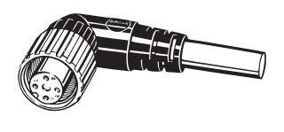
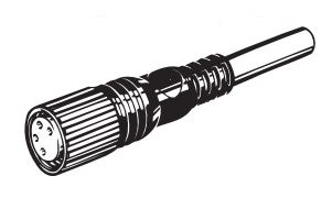
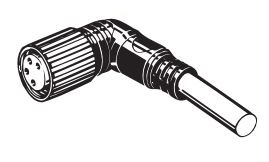
| Screw | Appearance *1 | Cable length 2m | Cable length 5m | |
| CablConnector model number | CablConnector model number | |||
| M12 | Straight | XS2F-D421-DA0-F | XS2F-D421-GA0-F | E2E-X[]D1-M1G(J) |
| L-shape | XS2F-D422-DA0-F | XS2F-D422-GA0-F | ||
| Straight | XS2F-D421-DC0-F | XS2F-D421-GC0-F | E2E-X[]E1-M1 E2E-X[]F1-M1 |
|
| L-shape | XS2F-D422-DC0-F | XS2F-D422-GC0-F | ||
| Straight | XS2F-D421-DD0 | XS2F-D421-GD0 | E2E-X[]D1-M1J-T | |
| E2E-X[]D1-M1 | ||||
| L-shape | XS2F-D422-DD0 | XS2F-D422-GD0 | E2E-X[]D1-M1J-T | |
| E2E-X[]D1-M1 | ||||
| Straight | XS2F-D421-D80-F | XS2F-D421-G80-F | E2E-X[]D2-M1G(J) | |
| E2E-X[]D2-M1J-T | ||||
| E2E-X[]D2-M1 | ||||
| E2E-X[]D1S-M1 | ||||
| E2E-X[]E2-M1 E2E-X[]F2-M1 |
||||
| L-shape | XS2F-D422-D80-F | XS2F-D422-G80-F | E2E-X[]D2-M1G(J) | |
| E2E-X[]D2-M1J-T | ||||
| E2E-X[]D2-M1 | ||||
| E2E-X[]D1S-M1 | ||||
| E2E-X[]E2-M1 E2E-X[]F2-M1 |
||||
| Straight | XS2F-A421-DB0-F | XS2F-A421-GB0-F | E2E-X[]Y1-M1 | |
| L-shape | XS2F-A422-DB0-F | XS2F-A422-GB0-F | ||
| Straight | XS2F-A421-D90-F | XS2F-A421-G90-F | E2E-X[]Y2-M1 | |
| Smartclick Connector, Straight |
XS5F-D421-D80-F | XS5F-D421-G80-F | E2E-X[]D1-M1TGJ(-US) | |
| E2E-X[]D2-M1TGJ-US | ||||
| Smartclick Connector, Straight Oil-resistant Reinforced Cables |
XS5F-D421-D80-P | XS5F-D421-G80-P | E2E-X[]D1-M1TGJ-U | |
| E2E-X[]D2-M1TGJ-U | ||||
| M8 | Straight | XS3F-M421-402-A | XS3F-M421-405-A | E2E-X[]D1-M3G |
| E2E-X[]D2-M3G | ||||
| E2E-X[]E1-M3 E2E-X[]F1-M3 |
||||
| E2E-X[]E2-M3 E2E-X[]F2-M3 |
||||
| L-shape | XS3F-M422-402-A | XS3F-M422-405-A | E2E-X[]D1-M3G | |
| E2E-X[]D2-M3G | ||||
| E2E-X[]E1-M3 E2E-X[]F1-M3 |
||||
| E2E-X[]E2-M3 E2E-X[]F2-M3 |
||||
Note: Refer to Introduction to Sensor I/O Connectors/Sensor Controllers for details and for information on Cable length
and Robotics Cables.
*1. Images of straight and L-shaped connectors.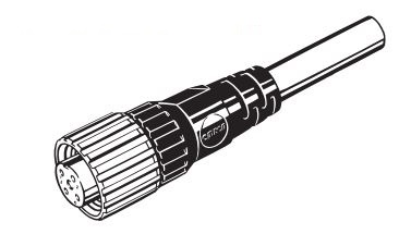
*2. Refer to Connection Diagrams on Data Sheet for information on Proximity Sensor and I/O Connector connections.
Specifications | Proximity Sensor Cylindrical - E2E
E2E-X[]D[] DC 2-Wire Models
| Size | M8 | M12 | |||
|---|---|---|---|---|---|
| Shielded | Shielded | Unshielded | Shielded | Unshielded | |
| Model | E2E-X2D[] | E2E-X4MD[] | E2E-X3D[] | E2E-X8MD[] | |
| Sensing distance | 2 mm ±10% | 4 mm ±10% | 3 mm ±10% | 8 mm ±10% | |
| Set distance *1 | 0 to 1.6 mm | 0 to 3.2 mm | 0 to 2.4 mm | 0 to 6.4 mm | |
| Differential travel | 15% max. of sensing distance | 10% max. of sensing distance | |||
| Detectable object | Ferrous metal (The sensing distance decreases with non-ferrous metal. Refer to Engineering Data on Data Sheet.) |
||||
| Standard sensing object | Iron, 8 × 8 × 1 mm |
Iron, 20 × 20 × 1 mm |
Iron, 12 × 12 × 1 mm |
Iron, 30 × 30 × 1 mm |
|
| Response frequency *2 | 1.5 kHz | 1 kHz | 0.8 kHz | ||
| Power supply voltage (operating voltage range) |
Standard Models: 12 to 24 VDC, ripple (p-p): 10% max. (10 to 30 VDC) US Models and Connector Models Used as UL-certified Models: 12 to 24 VDC, ripple (p-p): 10% max. (The operating voltage range is also the same.) *3 |
||||
| Leakage current | 0.8 mA max. | ||||
| Control output | Load current | 3 to 100 mA, Diagnostic output: 50 mA for -D1(5)S Models | |||
| Residual voltage *4 |
3 V max. (Load current: 100 mA, Cable length: 2 m, M1J-T Models only: 5 V max.) | ||||
| Indicators | D1 Models: Operation indicator (red) and setting indicator (green) D2 Models: Operation indicator (red) |
||||
| Operation mode (with sensing object approaching) |
D1 Models: NO D2 Models: NC Refer to the timing charts under I/O Circuit Diagrams on Data Sheet for details. |
||||
| Diagnostic output delay | 0.3 to 1 s | ||||
| Protection circuits | Surge suppressor, Load short-circuit protection (for control and diagnostic output) | ||||
| Ambient temperature range |
Operating: -25 to 70°C, Storage: -40 to 85°C (with no icing or condensation) | ||||
| Ambient humidity range | Operating/storage: 35% to 95% (with no condensation) | ||||
| Temperature influence | ±15% max. of sensing distance at 23°C in the temperature range of -25 to 70°C |
±10% max. of sensing distance at 23°C in the temperature range of -25 to 70°C |
|||
| Voltage influence | ±1% max. of sensing distance at rated voltage in the rated voltage ±15% range | ||||
| Insulation resistance | 50 MΩ min. (at 500 VDC) between current-carrying parts and case | ||||
| Dielectric strength | 1000 VAC, 50/60 Hz for 1 minute between current carry parts and case | ||||
| Vibration resistance | Destruction: 10 to 55 Hz, 1.5-mm double amplitude for 2 hours each in X, Y, and Z directions |
||||
| Shock resistance | Destruction: 500 m/s2 10 times each in X, Y, and Z directions |
Destruction: 1,000 m/s2 10 times each in X, Y, and Z directions |
|||
| Degree of protection | Pre-wired Models: IEC 60529 IP67, in-house standards: oil-resistant Connector Models: IEC 60529 IP67 |
||||
| Connection method | Pre-wired Models (Standard cable length: 2 m), Connector Models, or Pre-wired Connector Models (Standard cable length: 0.3 m) |
||||
| Weight (packed state) | Pre-wired Models |
Approx. 60 g | Approx. 70 g | ||
| Pre-wired Connector Models |
--- | Approx. 40 g | |||
| Connector Models |
Approx. 15 g | Approx. 25 g | |||
| Materi- als | Case | Stainless steel (SUS303) | Nickel-plated brass | ||
| Sensing surface | PBT | ||||
| Clamping nuts | Nickel-plated brass | ||||
| Toothed washer | Zinc-plated iron | ||||
| Accessories | Instruction manual | ||||
| Size | M18 | M30 | |||
|---|---|---|---|---|---|
| Shielded | Shielded | Unshielded | Shielded | Unshielded | |
| Model | E2E-X7D[] | E2E-X14MD[] | E2E-X10D[] | E2E-X20MD[] | |
| Sensing distance | 7 mm ±10% | 14 mm ±10% | 10 mm ±10% | 20 mm ±10% | |
| Set distance *1 | 0 to 5.6 mm | 0 to 11.2 mm | 0 to 8 mm | 0 to 16 mm | |
| Differential travel | 10% max. of sensing distance | ||||
| Detectable object | Ferrous metal (The sensing distance decreases with non-ferrous metal. Refer to Engineering Data on Data Sheet.) |
||||
| Standard sensing object | Iron, 18 × 18 × 1 mm |
Iron, 30 × 30 × 1 mm | Iron, 54 × 54 × 1 mm |
||
| Response frequency *2 | 0.5 kHz | 0.4 kHz | 0.1 kHz | ||
| Power supply voltage (operating voltage range) |
Standard Models: 12 to 24 VDC, ripple (p-p): 10% max. (10 to 30 VDC) US Models and Connector Models Used as UL-certified Models: 12 to 24 VDC, ripple (p-p): 10% max. (The operating voltage range is also the same.) *3 |
||||
| Leakage current | 0.8 mA max. | ||||
| Control output | Load current | 3 to 100 mA, Diagnostic output: 50 mA for -D1(5)S Models | |||
| Residual voltage *4 |
3 V max. (Load current: 100 mA, Cable length: 2 m, M1J-T Models only: 5 V max.) | ||||
| Indicators | D1 Models: Operation indicator (red) and setting indicator (green) D2 Models: Operation indicator (red) |
||||
| Operation mode (with sensing object approaching) |
D1 Models: NO D2 Models: NC Refer to the timing charts under I/O Circuit Diagrams on Data Sheet for details. |
||||
| Diagnostic output delay | 0.3 to 1 s | ||||
| Protection circuits | Surge suppressor, Load short-circuit protection (for control and diagnostic output) | ||||
| Ambient temperature range |
Operating: -25 to 70°C, Storage: -40 to 85°C (with no icing or condensation) | ||||
| Ambient humidity range | Operating/storage: 35% to 95% (with no condensation) | ||||
| Temperature influence | ±10% max. of sensing distance at 23°C in the temperature range of -25 to 70°C | ||||
| Voltage influence | ±1% max. of sensing distance at rated voltage in the rated voltage ±15% range | ||||
| Insulation resistance | 50 MΩ min. (at 500 VDC) between current-carrying parts and case | ||||
| Dielectric strength | 1000 VAC, 50/60 Hz for 1 minute between current carry parts and case | ||||
| Vibration resistance | Destruction: 10 to 55 Hz, 1.5-mm double amplitude for 2 hours each in X, Y, and Z directions |
||||
| Shock resistance | Destruction: 1,000 m/s2 10 times each in X, Y, and Z directions | ||||
| Degree of protection | Pre-wired Models: IEC 60529 IP67, in-house standards: oil-resistant Connector Models: IEC 60529 IP67 |
||||
| Connection method | Pre-wired Models (Standard cable length: 2 m), Connector Models, or Pre-wired Connector Models (Standard cable length: 0.3 m) |
||||
| Weight (packed state) | Pre-wired Models |
Approx. 130 g | Approx. 175 g | ||
| Pre-wired Connector Models |
Approx. 70 g | Approx. 110 g | |||
| Connector Models |
Approx. 40 g | Approx. 90 g | |||
| Materi- als | Case | Nickel-plated brass | |||
| Sensing surface | PBT | ||||
| Clamping nuts | Nickel-plated brass | ||||
| Toothed washer | Zinc-plated iron | ||||
| Accessories | Instruction manual | ||||
*1. Use the E2E within the range in which the setting indicator (green LED) is ON (except D2 Models).
*2. The response frequency is an average value.
Measurement conditions are as follows: standard sensing object, a distance of twice the standard sensing object,
and a set distance of half the sensing distance.
*3. For the information on UL-certified connector models, refer to your OMRON website.
*4. The residual voltage of each M1J-T Model is 5 V. When connecting to a device, make sure that the device can
withstand the residual voltage. (Refer to page 26 for details.)
E2E-X[]Y[] AC 2-Wire Models
| Size | M8 | M12 | |||
|---|---|---|---|---|---|
| Shielded | Shielded | Unshielded | Shielded | Unshielded | |
| Model | E2E-X1R5Y[] | E2E-X2MY[] | E2E-X2Y[] | E2E-X5MY[] | |
| Sensing distance | 1.5 mm ±10% | 2 mm ±10% | 5 mm ±10% | ||
| Set distance | 0 to 1.2 mm | 0 to 1.6 mm | 0 to 4 mm | ||
| Differential travel | 10% max. of sensing distance | ||||
| Detectable object | Ferrous metal (The sensing distance decreases with non-ferrous metal. Refer to Engineering Data on Data Sheet.) |
||||
| Standard sensing object | Iron, 8 × 8 × 1 mm |
Iron, 12 × 12 × 1 mm | Iron, 15 × 15 × 1 mm |
||
| Response frequency | 25 Hz | ||||
| Power supply voltage (operating voltage range) *1 |
24 to 240 VAC (20 to 264 VAC), 50/60 Hz | ||||
| Leakage current | 1.7 mA max. | ||||
| Control output | Load current *2 | 5 to 100 mA | 5 to 200 mA | ||
| Residual voltage | Refer to Engineering Data on Data Sheet. | ||||
| Indicators | Operation indicator (red) | ||||
| Operation mode (with sensing object approaching) |
Y1 Models: NO Y2 Models: NC Refer to the timing charts under I/O Circuit Diagrams on Data Sheet for details. |
||||
| Protection circuits | Surge suppressor | ||||
| Ambient temperature range *1 *2 |
Operating/Storage: -25 to 70°C (with no icing or condensation) |
Operating/Storage: -40 to 85°C (with no icing or condensation) |
|||
| Ambient humidity range | Operating/storage: 35% to 95% (with no condensation) | ||||
| Temperature influence | ±10% max. of sensing distance at 23°C in the temperature range of -25 to 70°C |
±15% max. of sensing distance at 23°C in the temperature range of -40 to 85°C, ±10% max. of sensing distance at 23°C in the temperature range of -25 to 70°C |
|||
| Voltage influence | ±1% max. of sensing distance at rated voltage in the rated voltage ±15% range | ||||
| Insulation resistance | 50 MΩ min. (at 500 VDC) between current-carrying parts and case | ||||
| Dielectric strength | 4,000 VAC (M8 Models: 2,000 VAC), 50/60 Hz for 1 min between current-carrying parts and case |
||||
| Vibration resistance | Destruction: 10 to 55 Hz, 1.5-mm double amplitude for 2 hours each in X, Y, and Z directions |
||||
| Shock resistance | Destruction: 500 m/s2 10 times each in X, Y, and Z directions |
Destruction: 1,000 m/s2 10 times each in X, Y, and Z directions |
|||
| Degree of protection | Pre-wired Models: IEC 60529 IP67, in-house standards: oil-resistant Connector Models: IEC 60529 IP67 |
||||
| Connection method | Pre-wired Models (Standard cable length: 2 m) and Connector Models | ||||
| Weight (packed state) | Pre-wired Models Model |
Approx. 60 g | Approx. 70 g | ||
| Connector Models | Approx. 15 g | Approx. 25 g | |||
| Materials | Case | Stainless steel (SUS303) | Nickel-plated brass | ||
| Sensing surface | PBT | ||||
| Clamping nuts | Nickel-plated brass | ||||
| Toothed washer | Zinc-plated iron | ||||
| Accessories | Instruction manual | ||||
| Size | M18 | M30 | |||
|---|---|---|---|---|---|
| Shielded | Shielded | Unshielded | Shielded | Unshielded | |
| Model | E2E-X5Y[] | E2E-X10MY[] | E2E-X10Y[] | E2E-X18MY[] | |
| Sensing distance | 5 mm ±10% | 10 mm ±10% | 18 mm ±10% | ||
| Set distance | 0 to 4 mm | 0 to 8 mm | 0 to 14 mm | ||
| Differential travel | 10% max. of sensing distance | ||||
| Detectable object | Ferrous metal (The sensing distance decreases with non-ferrous metal. Refer to Engineering Data on Data Sheet.) |
||||
| Standard sensing object | Iron, 18 × 18 × 1 mm |
Iron, 30 × 30 × 1 mm | Iron, 54 × 54 × 1 mm |
||
| Response frequency | 25 Hz | ||||
| Power supply voltage (operating voltage range) *1 |
24 to 240 VAC (20 to 264 VAC), 50/60 Hz | ||||
| Leakage current | 1.7 mA max. | ||||
| Control output | Load current *2 | 5 to 300 mA | |||
| Residual voltage | Refer to Engineering Data on Data Sheet. | ||||
| Indicators | Operation indicator (red) | ||||
| Operation mode (with sensing object approaching) |
Y1 Models: NO Y2 Models: NC Refer to the timing charts under I/O Circuit Diagrams on Data Sheet for details. |
||||
| Protection circuits | Surge suppressor | ||||
| Ambient temperature range *1 *2 |
Operating/Storage: -40 to 85°C (with no icing or condensation) | ||||
| Ambient humidity range | Operating/storage: 35% to 95% (with no condensation) | ||||
| Temperature influence | ±15% max. of sensing distance at 23°C in the temperature range of -40 to 85°C, ±10% max. of sensing distance at 23°C in the temperature range of -25 to 70°C |
||||
| Voltage influence | ±1% max. of sensing distance at rated voltage in the rated voltage ±15% range | ||||
| Insulation resistance | 50 MΩ min. (at 500 VDC) between current-carrying parts and case | ||||
| Dielectric strength | 4,000 VAC (M8 Models: 2,000 VAC), 50/60 Hz for 1 min between current-carrying parts and case |
||||
| Vibration resistance | Destruction: 10 to 55 Hz, 1.5-mm double amplitude for 2 hours each in X, Y, and Z directions |
||||
| Shock resistance | Destruction: 1,000 m/s2 10 times each in X, Y, and Z directions | ||||
| Degree of protection | Pre-wired Models: IEC 60529 IP67, in-house standards: oil-resistant Connector Models: IEC 60529 IP67 |
||||
| Connection method | Pre-wired Models (Standard cable length: 2 m) and Connector Models | ||||
| Weight (packed state) | Pre-wired Models Model |
Approx. 130 g | Approx. 175 g | ||
| Connector Models | Approx. 40 g | Approx. 90 g | |||
| Materials | Case | Stainless steel (SUS303) | Nickel-plated brass | ||
| Sensing surface | PBT | ||||
| Clamping nuts | Nickel-plated brass | ||||
| Toothed washer | Zinc-plated iron | ||||
| Accessories | Instruction manual | ||||
*1. When supplying 24 VAC to any of the above models, make sure that the operating ambient temperature range is at
least −25°C.
*2. When using an M18 or M30 Connector Model at an ambient temperature between 70 and 85°C, make sure that the
Sensor has a control output (load current) of 5 to 200 mA max.
E2E-X[]T1 AC/DC 2-Wire Models
| Size | M12 | M18 | M30 | |
|---|---|---|---|---|
| Shielded | Shielded | |||
| Model | E2E-X3T1 | E2E-X7T1 | E2E-X10T1 | |
| Sensing distance | 3 mm ±10% | 7 mm ±10% | 10 mm ±10% | |
| Set distance | 0 to 2.4 mm | 0 to 5.6 mm | 0 to 8 mm | |
| Differential travel | 10% max. of sensing distance | |||
| Detectable object | Ferrous metal (The sensing distance decreases with non-ferrous metal. Refer to Engineering Data on Data Sheet.) |
|||
| Standard sensing object | Iron, 12 × 12 × 1 mm | Iron, 18 × 18 × 1 mm | Iron, 30 × 30 × 1 mm | |
| Response frequency *1 | DC | 1 kHz | 0.5 kHz | 0.4 kHz |
| AC | 25 Hz | |||
| Power supply voltage (operating voltage range) *2 |
24 to 240 VDC (20 to 264 VDC) 48 to 240 VAC (40 to 264 VAC) |
|||
| Leakage current | DC: 1 mA max. AC: 2 mA max. |
|||
| Control output | Load current | 5 to 100 mA | ||
| Residual voltage |
DC: 6 V max. (Load current: 100 mA, Cable length: 2 m) AC: 10 V max. (Load current: 5 mA, Cable length: 2 m) |
|||
| Indicators | Operation indicator (red), Setting indicator (green) | |||
| Operation mode (with sensing object approaching) |
NO (Refer to the timing charts under I/O Circuit Diagrams on Data Sheet for details.) | |||
| Protection circuits | Load short-circuit protection (20 to 40 VDC only), Surge suppressor | |||
| Ambient temperature range | Operating: -25 to 70°C, Storage: -40 to 85°C (with no icing or condensation) | |||
| Ambient humidity range | Operating/Storage: 35% to 95% (with no condensation) | |||
| Temperature influence | ±10% max. of sensing distance at 23°C in the temperature range of -25 to 70°C | |||
| Voltage influence | ±1% max. of sensing distance at rated voltage in the rated voltage ±15% range | |||
| Insulation resistance | 50 MΩ min. (at 500 VDC) between current-carrying parts and case | |||
| Dielectric strength | 4,000 VAC, 50/60 Hz for 1 minute between current-carrying parts and case | |||
| Vibration resistance | Destruction: 10 to 55 Hz, 1.5-mm double amplitude for 2 hours each in X, Y, and Z directions |
|||
| Shock resistance | Destruction: 1,000 m/s2 10 times each in X, Y, and Z directions | |||
| Degree of protection | IEC 60529 IP67, in-house standards: oil-resistant | |||
| Connection method | Pre-wired Models (Standard cable length: 2 m) | |||
| Weight (packed state) | Approx. 80 g | Approx. 140 g | Approx. 190 g | |
| Materials | Case | Nickel-plated brass | ||
| Sensing surface | PBT | |||
| Clamping nuts | Nickel-plated brass | |||
| Toothed washer | Zinc-plated iron | |||
| Accessories | Instruction manual | |||
*1. The response frequency is an average value. Measurement conditions are as follows: standard sensing object, a
distance of twice the standard sensing object, and a set distance of half the sensing distance.
*2. Power Supply Voltage Waveform:
Use a sine wave for the power supply. Using a rectangular AC power supply may result in faulty reset.
E2E-X[]E[]/F[] DC 3-Wire Models
| Size | M8 | M12 | |||
|---|---|---|---|---|---|
| Shielded | Shielded | Unshielded | Shielded | Unshielded | |
| Model | E2E-X1R5E[]/F[] | E2E-X2ME[]/F[] | E2E-X2E[]/F[] | E2E-X5ME[]/F[] | |
| Sensing distance | 1.5 mm ±10% | 2 mm ±10% | 5 mm ±10% | ||
| Set distance | 0 to 1.2 mm | 0 to 1.6 mm | 0 to 4 mm | ||
| Differential travel | 10% max. of sensing distance | ||||
| Detectable object | Ferrous metal (The sensing distance decreases with non-ferrous metal. Refer to Engineering Data on Data Sheet.) |
||||
| Standard sensing object | Iron, 8 × 8 × 1 mm |
Iron, 12 × 12 × 1 mm | Iron, 15 × 15 × 1 mm |
||
| Response frequency *1 | 2 kHz | 0.8 kHz | 1.5 kHz | 0.4 kHz | |
| Power supply voltage (operating voltage range) *2 |
12 to 24 VDC, ripple(p-p): 10% max. (10 to 30 VDC) Connector Models Used as UL-certified Models: 12 to 24 VDC, ripple (p-p): 10% max. (The operating voltage range is also the same.) *3 |
||||
| Current consumption | 13 mA max. | ||||
| Control output | Load current *2 | 200 mA max. | |||
| Residual voltage | 2 V max. (Load current: 200 mA, Cable length: 2 m) | ||||
| Indicators | Operation indicator (red) | ||||
| Operation mode (with sensing object approaching) |
E1/F1 Models: NO E2/F2 Models: NC Refer to the timing charts under I/O Circuit Diagrams on Data Sheet for details. |
||||
| Protection circuits | Load short-circuit protection, Surge suppressor, Reverse polarity protection | ||||
| Ambient temperature range *2 |
Operating/Storage: -40 to 85°C (with no icing or condensation) | ||||
| Ambient humidity range | Operating/Storage: 35% to 95% (with no condensation) | ||||
| Temperature influence | ±15% max. of sensing distance at 23°C in the temperature range of -40 to 85°C ±10% max. of sensing distance at 23°C in the temperature range of -25 to 70°C |
||||
| Voltage influence | ±1% max. of sensing distance at rated voltage in the rated voltage ±15% range | ||||
| Insulation resistance | 50 MΩ min. (at 500 VDC) between current-carrying parts and case | ||||
| Dielectric strength | 1,000 VAC, 50/60 Hz for 1 minute between current carry parts and case | ||||
| Vibration resistance | Destruction: 10 to 55 Hz, 1.5-mm double amplitude for 2 hours each in X, Y, and Z directions |
||||
| Shock resistance | Destruction: 500 m/s2 10 times each in X, Y, and Z directions |
Destruction: 1,000 m/s2 10 times each in X, Y, and Z directions |
|||
| Degree of protection | Pre-wired Models: IEC 60529 IP67, in-house standards: oil-resistant Connector Models: IEC 60529 IP67 |
||||
| Connection method | Pre-wired Models (Standard cable length: 2 m) and Connector Models | ||||
| Weight (packed state) | Pre-wired Models | Approx. 65 g | Approx. 75 g | ||
| Connector Models |
Approx. 15 g | Approx. 25 g | |||
| Materials | Case | Stainless steel (SUS303) | Nickel-plated brass | ||
| Sensing surface | PBT | ||||
| Clamping nuts | Nickel-plated brass | ||||
| Toothed washer | Zinc-plated iron | ||||
| Accessories | Instruction manual | ||||
| Size | M18 | M30 | |||
|---|---|---|---|---|---|
| Shielded | Shielded | Unshielded | Shielded | Unshielded | |
| Model | E2E-X5E[]/F[] | E2E-X10ME[]/F[] | E2E-X10E[]/F[] | E2E-X18ME[]/F[] | |
| Sensing distance | 5 mm ±10% | 10 mm ±10% | 18 mm ±10% | ||
| Set distance | 0 to 4 mm | 0 to 8 mm | 0 to 14 mm | ||
| Differential travel | 10% max. of sensing distance | ||||
| Detectable object | Ferrous metal (The sensing distance decreases with non-ferrous metal. Refer to Engineering Data on Data Sheet.) |
||||
| Standard sensing object | Iron, 18 × 18 × 1 mm |
Iron, 30 × 30 × 1 mm | Iron, 54 × 54 × 1 mm |
||
| Response frequency *1 | 0.6 kHz | 0.2 kHz | 0.4 kHz | 0.1 kHz | |
| Power supply voltage (operating voltage range) *2 |
12 to 24 VDC, ripple(p-p): 10% max. (10 to 30 VDC) Connector Models Used as UL-certified Models: 12 to 24 VDC, ripple (p-p): 10% max. (The operating voltage range is also the same.) *3 |
||||
| Current consumption | 13 mA max. | ||||
| Control output | Load current *2 | 200 mA max. | |||
| Residual voltage | 2 V max. (Load current: 200 mA, Cable length: 2 m) | ||||
| Indicators | Operation indicator (red) | ||||
| Operation mode (with sensing object approaching) |
E1/F1 Models: NO E2/F2 Models: NC Refer to the timing charts under I/O Circuit Diagrams on Data Sheet for details. |
||||
| Protection circuits | Load short-circuit protection, Surge suppressor, Reverse polarity protection | ||||
| Ambient temperature range *2 |
Operating/Storage: -40 to 85°C (with no icing or condensation) | ||||
| Ambient humidity range | Operating/Storage: 35% to 95% (with no condensation) | ||||
| Temperature influence | ±15% max. of sensing distance at 23°C in the temperature range of -40 to 85°C ±10% max. of sensing distance at 23°C in the temperature range of -25 to 70°C |
||||
| Voltage influence | ±1% max. of sensing distance at rated voltage in the rated voltage ±15% range | ||||
| Insulation resistance | 50 MΩ min. (at 500 VDC) between current-carrying parts and case | ||||
| Dielectric strength | 1,000 VAC, 50/60 Hz for 1 minute between current carry parts and case | ||||
| Vibration resistance | Destruction: 10 to 55 Hz, 1.5-mm double amplitude for 2 hours each in X, Y, and Z directions |
||||
| Shock resistance | Destruction: 1,000 m/s2 10 times each in X, Y, and Z directions | ||||
| Degree of protection | Pre-wired Models: IEC 60529 IP67, in-house standards: oil-resistant Connector Models: IEC 60529 IP67 |
||||
| Connection method | Pre-wired Models (Standard cable length: 2 m) and Connector Models | ||||
| Weight (packed state) | Pre-wired Models | Approx. 150 g | Approx. 195 g | ||
| Connector Models |
Approx. 40 g | Approx. 90 g | |||
| Materials | Case | Nickel-plated brass | |||
| Sensing surface | PBT | ||||
| Clamping nuts | Nickel-plated brass | ||||
| Toothed washer | Zinc-plated iron | ||||
| Accessories | Instruction manual | ||||
*1. The response frequency is an average value. Measurement conditions are as follows: standard sensing object, a
distance of twice the standard sensing object, and a set distance of half the sensing distance.
*2. When using an M8 Model at an ambient temperature between 70 and 85°C, supply 10 to 30 VDC to the Sensor and
make sure that the Sensor has a control output of 100 mA maximum.
*3. For the information on UL-certified connector models, refer to your OMRON website.
Dimensions | Proximity Sensor Cylindrical - E2E
(Unit: mm)
Tolerance class IT16 applies to dimensions in this data sheet unless otherwise specified.
Main Units
Model Number-Dimensions Drawing Number Lookup Table
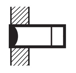
Pre-wired Models (Shielded)
Diagram 1
E2E-X2D[]
E2E-X1R5E[]/F[]
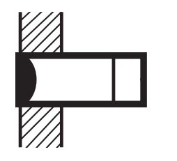
Diagram 3
E2E-X1R5Y[]
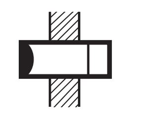
Diagram 5
E2E-X3D[]
E2E-X2E[]/F[]
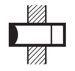
Diagram 7
E2E-X2Y[]
Pre-wired Models (Unshielded)
Diagram 2
E2E-X4MD[]
E2E-X2ME[]/F[]
Diagram 4
E2E-X2MY[]
Diagram 6
E2E-X8MD[]
E2E-X5ME[]/F[]
Diagram 8
E2E-X5MY[]
Mounting Hole Dimensions
Pre-wired Models (Shielded)
Diagram 9
E2E-X3T1
Diagram 10
E2E-X7D[]/E2E-X5E[]/F[]
E2E-X5Y[]/E2E-X7T1
Diagram 12
E2E-X10D[]/E2E-X10E[]/F[]
E2E-X10Y[]/E2E-X10T1
Pre-wired Models (Unshielded)
Diagram 11
E2E-X14MD[]/E2E-X10ME[]/F[]
E2E-X10MY[]
Diagram 13
E2E-X20MD[]/E2E-X18ME[]/F[]
E2E-X18MY[]
Mounting Hole Dimensions
M8 Connector Models (Shielded)
Diagram 24
E2E-X2D[]-M3G/E2E-X1R5E[]-M3/X1RF[]-M3
M8 Connector Models (Unshielded)
Diagram 25
E2E-X4MD[]-M3G/E2E-X2ME[]-M3/X2MF[]-M3
M12 Connector Models (Shielded)
Diagram 14
E2E-X2D[]-M1(G)
E2E-X1R5E[]-M1/E2E-X1R5F[]-M1
Diagram 16
E2E-X3D[]-M1(G)
E2E-X2E[]-M1/E2E-X2F[]-M1
Diagram 18
E2E-X2Y[]-M1
Diagram 20
E2E-X7D[]-M1(G)/E2E-X5E[]-M1/X5F[]-M1
E2E-X5Y[]-M1
Diagram 22
E2E-X10D[]-M1(G)/E2E-X10E[]-M1/X10F[]-M1
E2E-X10Y[]-M1
M12 Connector Models (Unshielded)
Diagram 15
E2E-X4MD[]-M1(G)
E2E-X2ME[]-M1/E2E-X2MF[]-M1
Diagram 17
E2E-X8MD[]-M1(G)
E2E-X5ME[]-M1/E2E-X5MF[]-M1
Diagram 19
E2E-X5MY[]-M1
Diagram 21
E2E-X14MD[]-M1(G)/E2E-X10ME[]-M1/X10MF[]-M1
E2E-X10MY[]M1
Diagram 23
E2E-X20MD[]-M1(G)/E2E-X18ME[]-M1/X18MF[]-M1
E2E-X18MY[]-M1
Mounting Hole Dimensions
Pre-wired Connector Models (Shielded)
Diagram 26
E2E-X2D[]-M1TGJ-U *3
E2E-X2D1-M1TGJ
E2E-X2D[]-M1TGJ-US
Diagram 27
E2E-X3D[]-M1GJ
E2E-X3D1-M1J-T
E2E-X3D[]-M1TGJ-U *3
E2E-X3D1-M1TGJ
E2E-X3D[]-M1TGJ-US
Diagram 28
E2E-X7D[]-M1GJ
E2E-X7D[]-M1J-T
E2E-X7D[]-M1TGJ-U *3
E2E-X7D1-M1TGJ
E2E-X7D[]-M1TGJ-US
Diagram 29
E2E-X10D[]-M1GJ
E2E-X10D[]-M1J-T
E2E-X10D[]-M1TGJ-U *3
E2E-X10D1-M1TGJ
E2E-X10D[]-M1TGJ-US
Pre-wired Connector Models (Unshielded)
Diagram 30
E2E-X4MD[]-M1TGJ-US
Diagram 31
E2E-X8MD1-M1GJ
E2E-X8MD1-M1TGJ
E2E-X8MD[]-M1TGJ-US
Diagram 32
E2E-X14MD[]-M1GJ
E2E-X14MD1-M1TGJ
E2E-X14MD[]-M1TGJ-US
Diagram 33
E2E-X20MD1-M1GJ
E2E-X20MD1-M1TGJ
E2E-X20MD[]-M1TGJ-US
Mounting Hole Dimensions
Dimensions for Proximity Sensors with Sensor I/O Connectors
Dimensions with the XS2F/XS5F Connected
* The overall length of the Sensor is different between AC and DC Models for Sensors with diameters of M12. This will
change the dimension when the I/O Connector is connected.
Dimensions with the XS3F Connected
Features | Proximity Sensor Cylindrical - E2E
- Standard Sensors for detecting ferrous metals.
- Wide array of variations. Ideal for a variety of applications.
- Models with different frequencies are also available to prevent mutual interference.
- Superior environment resistance with standard cable made of oil resistant PVC and sensing surface made of material that resists cutting oil.
- Useful to help prevent disconnection. Cable protector provided as a standard feature.
Properties | Proximity Sensor Cylindrical - E2E
| Proximity Sensor Cylindrical | E2E |
|---|---|
| Model type | DC 2-wire, DC 3-wire, AC 2-wire |
| Sensing Distance (mm) | 0.8, 1.2, 1.5, 2, 3, 4, 5, 7, 8, 10, 14, 18, 20 |
| Housing Size | 3 dia., 4 dia., 6.5 dia., M4, M5, M8, M12, M18, M30 |
| Housing material | Nickel Plated Brass-(NPB), Stainless Steel-(SUS) |
| Power | 10 – 30 VDC |
| 12 – 24 VDC | |
| 24 – 240 VAC | |
| Degree of Protection | IP67, IP69K |
พร็อกซิมิตี้สวิตซ์ทรงกระบอก - E2E
ดาวน์โหลดไฟล์ PDF เลือกรุ่นสินค้า | Proximity Sensor Cylindrical - E2E
รุ่น 2 สาย
รุ่น DC 2 สาย ประเภท Shielded โดยที่ไม่มีเอาต์พุต Self-diagnostic
| ลักษณะ | ระยะตรวจจับ | วิธีการตรวจจับ | ข้อมูลจำเพาะสาย | ขั้ว | โหมดการทำงาน | การกำหนดพิน | รหัสคอนเนคเตอร์ที่ใช้ได้ *2 | รุ่นสินค้า |
|---|---|---|---|---|---|---|---|---|
| M8 | 2 มม. | คอนเนคเตอร์ Smartclick มีสายในตัว M12 (0.3 ม.) | PUR (เพิ่มความทนต่อน้ำมัน) | มี | NO | 1: +V, 4: 0 V |
H | E2E-X2D1-M1TGJ-U 0.3M |
| NC | 1: +V, 2: 0 V |
E2E-X2D2-M1TGJ-U 0.3M | ||||||
| PVC (ทนต่อน้ำมัน) |
NO | 1: +V, 4: 0 V |
G | E2E-X2D1-M1TGJ 0.3M | ||||
| มีสายในตัว (2 ม.) | PUR (เพิ่มความทนต่อน้ำมัน) | NO | --- | --- | E2E-X2D1-U 2M | |||
| NC | E2E-X2D2-U 2M | |||||||
| PVC (ทนต่อน้ำมัน) |
NO | E2E-X2D1-N 2M | ||||||
| NC | E2E-X2D2-N 2M | |||||||
| คอนเนคเตอร์ M12 | --- | NO | 1: +V, 4: 0 V |
A | E2E-X2D1-M1G | |||
| NC | 1: +V, 2: 0 V |
D | E2E-X2D2-M1G | |||||
| คอนเนคเตอร์ M8 | --- | NO | 1: +V, 4: 0 V |
I | E2E-X2D1-M3G | |||
| NC | 1: +V, 2: 0 V |
E2E-X2D2-M3G | ||||||
| M12 | 3 มม. | คอนเนคเตอร์ Smartclick มีสายในตัว M12 (0.3 ม.) | PUR (เพิ่มความทนต่อน้ำมัน) | มี | NO | 1: +V, 4: 0 V |
H | E2E-X3D1-M1TGJ-U 0.3M |
| NC | 1: +V, 2: 0 V |
E2E-X3D2-M1TGJ-U 0.3M | ||||||
| PVC (ทนต่อน้ำมัน) |
NO | 1: +V, 4: 0 V |
G | E2E-X3D1-M1TGJ 0.3M | ||||
| มีสายในตัว (2 ม.) | PUR (เพิ่มความทนต่อน้ำมัน) | NO | --- | --- | E2E-X3D1-U 2M | |||
| NC | E2E-X3D2-U 2M | |||||||
| PVC (ทนต่อน้ำมัน) |
NO | E2E-X3D1-N 2M *1 | ||||||
| NC | E2E-X3D2-N 2M | |||||||
| คอนเนคเตอร์ M12 | --- | NO | 1: +V, 4: 0 V |
A | E2E-X3D1-M1G *1 | |||
| NC | 1: +V, 2: 0 V |
D | E2E-X3D2-M1G | |||||
| คอนเนคเตอร์มาตราฐานมีสายในตัว M12 (0.3 ม.) | PVC (ทนต่อน้ำมัน) |
มี | NO | 1: +V, 4: 0 V |
A | E2E-X3D1-M1GJ 0.3M | ||
| NC | 1: +V, 2: 0 V |
D | E2E-X3D2-M1GJ 0.3M | |||||
| ไม่มี *3 | NO | (3, 4): (+V, 0 V) |
C | E2E-X3D1-M1J-T 0.3M | ||||
| NC | (1, 2): (+V, 0 V) |
D | --- | |||||
| M18 | 7 มม. | คอนเนคเตอร์ Smartclick มีสายในตัว M12 (0.3 ม.) | PUR (เพิ่มความทนต่อน้ำมัน) | มี | NO | 1: +V, 4: 0 V |
H | E2E-X7D1-M1TGJ-U 0.3M |
| NC | 1: +V, 2: 0 V |
E2E-X7D2-M1TGJ-U 0.3M | ||||||
| PVC (ทนต่อน้ำมัน) |
NO | 1: +V, 4: 0 V |
G | E2E-X7D1-M1TGJ 0.3M | ||||
| มีสายในตัว (2 ม.) | PUR (เพิ่มความทนต่อน้ำมัน) | NO | --- | --- | E2E-X7D1-U 2M | |||
| NC | E2E-X7D2-U 2M | |||||||
| PVC (ทนต่อน้ำมัน) |
NO | E2E-X7D1-N 2M *1 | ||||||
| NC | E2E-X7D2-N 2M | |||||||
| คอนเนคเตอร์ M12 | --- | NO | 1: +V, 4: 0 V |
A | E2E-X7D1-M1G *1 | |||
| NC | 1: +V, 2: 0 V |
D | E2E-X7D2-M1G | |||||
| คอนเนคเตอร์มาตราฐานมีสายในตัว M12 (0.3 ม.) | PVC (ทนต่อน้ำมัน) |
มี | NO | 1: +V, 4: 0 V |
A | E2E-X7D1-M1GJ 0.3M | ||
| NC | 1: +V, 2: 0 V |
D | E2E-X7D2-M1GJ 0.3M | |||||
| ไม่มี *3 | NO | (3, 4): (+V, 0 V) |
C | E2E-X7D1-M1J-T 0.3M | ||||
| NC | (1, 2): (+V, 0 V) |
D | E2E-X7D2-M1J-T 0.3M | |||||
| M30 | 10 มม. | คอนเนคเตอร์ Smartclick มีสายในตัว M12 (0.3 ม.) | PUR (เพิ่มความทนต่อน้ำมัน) | มี | NO | 1: +V, 4: 0 V |
H | E2E-X10D1-M1TGJ-U 0.3M |
| NC | 1: +V, 2: 0 V |
E2E-X10D2-M1TGJ-U 0.3M | ||||||
| PVC (ทนต่อน้ำมัน) |
NO | 1: +V, 4: 0 V |
G | E2E-X10D1-M1TGJ 0.3M | ||||
| มีสายในตัว (2 ม.) | PUR (เพิ่มความทนต่อน้ำมัน) | NO | --- | --- | E2E-X10D1-U 2M | |||
| NC | E2E-X10D2-U 2M | |||||||
| PVC (ทนต่อน้ำมัน) |
NO | E2E-X10D1-N 2M *1 | ||||||
| NC | E2E-X10D2-N 2M | |||||||
| คอนเนคเตอร์ M12 | --- | NO | 1: +V, 4: 0 V |
A | E2E-X10D1-M1G *1 | |||
| NC | 1: +V, 2: 0 V |
D | E2E-X10D2-M1G | |||||
| คอนเนคเตอร์มาตราฐานมีสายในตัว M12 (0.3 ม.) | PVC (ทนต่อน้ำมัน) |
มี | NO | 1: +V, 4: 0 V |
A | E2E-X10D1-M1GJ 0.3M | ||
| PVC (ทนต่อน้ำมัน) |
NC | 1: +V, 2: 0 V |
D | E2E-X10D2-M1GJ 0.3M | ||||
| PVC (ทนต่อน้ำมัน) |
ไม่มี *3 | NO | (3, 4): (+V, 0 V) |
C | E2E-X10D1-M1J-T 0.3M | |||
| PVC (ทนต่อน้ำมัน) |
NC | (1, 2): (+V, 0 V) |
D | E2E-X10D2-M1J-T 0.3M |
*1. นอกจากนี้ยังมีรุ่นที่มีความถี่แตกต่างกัน หมายเลขรุ่นคือ E2E-X[]D15 (ตัวอย่าง: E2E-X3D15-N 2M)
*2. อ้างอิงรายละเอียดจาก Data Sheet
*3. แรงดันตกค้างสำหรับรุ่นที่ไม่มีขั้วคือ 5 V ดังนั้นโปรดใช้ความระมัดระวังเกี่ยวกับเงื่อนไขการเชื่อมต่อโหลดการเชื่อมต่อ (เช่นแรงดันไฟฟ้า PLC ON) อ้างถึงเอกสารข้อมูล
รุ่น UL-recognized DC 2 สาย ประเภท Shielded โดยที่ไม่มีเอาต์พุต Self-diagnostic
| ลักษณะ | ระยะการตรวจจับ | วิธีการตรวจจัล | ข้อมูลจำเพาะของสาย | ขั้ว | โหมดการทำงาน | การกำหนดพิน | รหัสคอนเนคเตอร์ที่ใช้ได้ * | รุ่นสินค้า |
|---|---|---|---|---|---|---|---|---|
| M8 | 2 มม. | คอนเนคเตอร์ Smartclick มีสายในตัว M12 (0.3 ม.) | PVC (ทนต่อน้ำมัน) |
มี | NO | 1: +V, 4: 0 V |
G | E2E-X2D1-M1TGJ-US 0.3M |
| NC | 1: +V, 2: 0 V |
E2E-X2D2-M1TGJ-US 0.3M | ||||||
| มีสายในตัว (2 ม.) | NO | --- | --- | E2E-X2D1-US 2M | ||||
| NC | E2E-X2D2-US 2M | |||||||
| M12 | 3 มม. | คอนเนคเตอร์ Smartclick มีสายในตัว M12 (0.3 ม.) | NO | 1: +V, 4: 0 V |
G | E2E-X3D1-M1TGJ-US 0.3M | ||
| NC | 1: +V, 2: 0 V |
E2E-X3D2-M1TGJ-US 0.3M | ||||||
| มีสายในตัว (2 ม.) | NO | --- | --- | E2E-X3D1-US 2M | ||||
| NC | E2E-X3D2-US 2M | |||||||
| M18 | 7 มม. | คอนเนคเตอร์ Smartclick มีสายในตัว M12 (0.3 ม.) | NO | 1: +V, 4: 0 V |
G | E2E-X7D1-M1TGJ-US 0.3M | ||
| NC | 1: +V, 2: 0 V |
E2E-X7D2-M1TGJ-US 0.3M | ||||||
| มีสายในตัว (2 ม.) | NO | --- | --- | E2E-X7D1-US 2M | ||||
| NC | E2E-X7D2-US 2M | |||||||
| M30 | 10 มม. | คอนเนคเตอร์ Smartclick มีสายในตัว M12 (0.3 ม.) | NO | 1: +V, 4: 0 V |
G | E2E-X10D1-M1TGJ-US 0.3M | ||
| NC | 1: +V, 2: 0 V |
E2E-X10D2-M1TGJ-US 0.3M | ||||||
| มีสายในตัว (2 ม.) | NO | --- | --- | E2E-X10D1-US 2M | ||||
| NC | E2E-X10D2-US 2M |
* อ้างอิงรายละเอียดจาก Data Sheet
รุ่น DC 2 สาย ประเภท Unshielded โดยที่ไม่มีเอาต์พุต Self-diagnostic
| ลักษณะ | ระยะการตรวจจับ | วิธีการตรวจจับ | ข้อมูลจำเพาะของสาย | ขั้ว | โหมดการทำงาน | การกำหนดพิน | รหัสคอนเนคเตอร์ที่ใช้ได้ *2 | รุ่นสินค้า |
|---|---|---|---|---|---|---|---|---|
| M8 | 4 มม. | มีสายในตัว (2 ม.) | PVC (ทนต่อน้ำมัน) |
Yes | NO | --- | --- | E2E-X4MD1 2M |
| NC | E2E-X4MD2 2M | |||||||
| คอนเนคเตอร์ M12 | --- | NO | 1: +V, 4: 0 V |
A | E2E-X4MD1-M1G | |||
| NC | 1: +V, 2: 0 V |
D | E2E-X4MD2-M1G | |||||
| คอนเนคเตอร์ M8 | --- | NO | 1: +V, 4: 0 V |
I | E2E-X4MD1-M3G | |||
| NC | 1: +V, 2: 0 V |
E2E-X4MD2-M3G | ||||||
| M12 | 8 มม. | คอนเนคเตอร์ Smartclick มีสายในตัวM12 (0.3 ม.) | PVC (ทนต่อน้ำมัน) |
NO | 1: +V, 4: 0 V |
G | E2E-X8MD1-M1TGJ 0.3M | |
| มีสายในตัว (2 ม.) | PVC (ทนต่อน้ำมัน) |
NO | --- | --- | E2E-X8MD1 2M *1 | |||
| NC | E2E-X8MD2 2M | |||||||
| คอนเนคเตอร์ M12 | --- | NO | 1: +V, 4: 0 V |
A | E2E-X8MD1-M1G *1 | |||
| NC | 1: +V, 2: 0 V |
D | E2E-X8MD2-M1G | |||||
| คอนเนคเตอร์มาตราฐานมีสายในตัว M12 (0.3 ม.) | PVC (ทนต่อน้ำมัน) |
NO | 1: +V, 4: 0 V |
A | E2E-X8MD1-M1GJ 0.3M | |||
| NC | 1: +V, 2: 0 V |
D | --- | |||||
| M18 | 14 มม. | คอนเนคเตอร์ Smartclick มีสายในตัวM12 (0.3 ม.) | PVC (ทนต่อน้ำมัน) |
NO | 1: +V, 4: 0 V |
G | E2E-X14MD1-M1TGJ 0.3M | |
| มีสายในตัว (2 ม.) | PVC (ทนต่อน้ำมัน) |
NO | --- | --- | E2E-X14MD1 2M *1 | |||
| NC | E2E-X14MD2 2M | |||||||
| คอนเนคเตอร์ M12 | --- | NO | 1: +V, 4: 0 V |
A | E2E-X14MD1-M1G *1 | |||
| NC | 1: +V, 2: 0 V |
D | E2E-X14MD2-M1G | |||||
| คอนเนคเตอร์มาตราฐานมีสายในตัว M12 (0.3 ม.) | PVC (ทนต่อน้ำมัน) |
NO | 1: +V, 4: 0 V |
A | E2E-X14MD1-M1GJ 0.3M | |||
| NC | 1: +V, 2: 0 V |
D | E2E-X14MD2-M1GJ 0.3M | |||||
| M30 | 20 มม. | คอนเนคเตอร์ Smartclick มีสายในตัวM12 (0.3 ม.) | PVC (ทนต่อน้ำมัน) |
NO | 1: +V, 4: 0 V |
G | E2E-X20MD1-M1TGJ 0.3M | |
| มีสายในตัว (2 ม.) | PVC (ทนต่อน้ำมัน) |
NO | --- | --- | E2E-X20MD1 2M *1 | |||
| NC | E2E-X20MD2 2M | |||||||
| คอนเนคเตอร์ M12 | --- | NO | 1: +V, 4: 0 V |
A | E2E-X20MD1-M1G *1 | |||
| NC | 1: +V, 2: 0 V |
D | E2E-X20MD2-M1G | |||||
| คอนเนคเตอร์มาตราฐานมีสายในตัว M12 (0.3 ม.) | PVC (ทนต่อน้ำมัน) |
NO | 1: +V, 4: 0 V |
A | E2E-X20MD1-M1GJ 0.3M | |||
| NC | 1: +V, 2: 0 V |
D | --- |
*1. นอกจากนี้ยังมีรุ่นที่มีความถี่แตกต่างกันหมายเลขรุ่น คือ E2E-X[]D15 (ตัวอย่าง: E2E-X8MD15 2M)
*2. อ้างอิงรายละเอียดจาก Data Sheet
รุ่น UL-recognized DC 2 สาย ประเภท Unshielded โดยที่ไม่มีเอาต์พุต Self-diagnostic
| ลักษณะ | ระยะการตรวจจับ | วิธีการตรวจจับ | ข้อมูลจำเพาะของสาย | ขั้ว | โหมดการทำงาน | การกำหนดพิน | รหัสคอนเนตเตอร์ที่ใช้ได้ * | รุ่นสินค้า |
|---|---|---|---|---|---|---|---|---|
| M8 | 4 มม. | คอนเนคเตอร์ Smartclick มีสายในตัว M12 (0.3 ม.) | PVC (ทนต่อน้ำมัน) |
มี | NO | 1: +V, 4: 0 V |
G | E2E-X4MD1-M1TGJ-US 0.3M |
| NC | 1: +V, 2: 0 V |
E2E-X4MD2-M1TGJ-US 0.3M | ||||||
| มีสายในตัว (2 ม.) | NO | --- | --- | E2E-X4MD1-US 2M | ||||
| NC | E2E-X4MD2-US 2M | |||||||
| M12 | 8 มม. | คอนเนคเตอร์ Smartclick มีสายในตัว M12 (0.3 ม.) | NO | 1: +V, 4: 0 V |
G | E2E-X8MD1-M1TGJ-US 0.3M | ||
| NC | 1: +V, 2: 0 V |
E2E-X8MD2-M1TGJ-US 0.3M | ||||||
| มีสายในตัว (2 ม.) | NO | --- | --- | E2E-X8MD1-US 2M | ||||
| NC | E2E-X8MD2-US 2M | |||||||
| M18 | 14 มม. | คอนเนคเตอร์ Smartclick มีสายในตัว M12 (0.3 ม.) | NO | 1: +V, 4: 0 V |
G | E2E-X14MD1-M1TGJ-US 0.3M | ||
| NC | 1: +V, 2: 0 V |
E2E-X14MD2-M1TGJ-US 0.3M | ||||||
| มีสายในตัว (2 ม.) | NO | --- | --- | E2E-X14MD1-US 2M | ||||
| NC | E2E-X14MD2-US 2M | |||||||
| M30 | 20 มม. | คอนเนคเตอร์ Smartclick มีสายในตัว M12 (0.3 ม.) | NO | 1: +V, 4: 0 V |
G | E2E-X20MD1-M1TGJ-US 0.3M | ||
| NC | 1: +V, 2: 0 V |
E2E-X20MD2-M1TGJ-US 0.3M | ||||||
| มีสายในตัว (2 ม.) | NO | --- | --- | E2E-X20MD1-US 2M | ||||
| NC | E2E-X20MD2-US 2M |
* อ้างอิงรายละเอียดจาก Data Sheet
รุ่น DC 2 สาย ประเภท Shielded พร้อมกับ Self-diagnostic
| ลักษณะ | ระยะการตรวจจับ | วิธีการตรวจจับ | ข้อมูลจำเพาะของวาย | ขั้ว | โหมดการทำงาน | การกำหนดพิน | รหัสคอนเนคเตอร์ที่ใช้ได้ *2 | รุ่นสินค้า |
|---|---|---|---|---|---|---|---|---|
| M12 | 3 มม. | มีสายในตัว (2 ม.) | PVC (ทนต่อน้ำมัน) |
มี | NO | --- | --- | E2E-X3D1S 2M *1 |
| คอนเนคเตอร์ M12 | --- | 2: +V and diagnostic output 3: 0 V 4: +V and control output |
D | E2E-X3D1S-M1 | ||||
| M18 | 7 มม. | มีสายในตัว (2 ม.) | PVC (ทนต่อน้ำมัน) |
--- | --- | E2E-X7D1S 2M *1 | ||
| คอนเนคเตอร์ M12 | --- | 2: +V and diagnostic output 3: 0 V 4: +V and control output |
D | E2E-X7D1S-M1 | ||||
| M30 | 10 มม. | มีสายในตัว (2 ม.) | PVC (ทนต่อน้ำมัน) |
--- | --- | E2E-X10D1S 2M *1 | ||
| คอนเนคเตอร์ M12 | --- | 2: +V and diagnostic output 3: 0 V 4: +V and control output |
D | E2E-X10D1S-M1 |
*1. นอกจากนี้ยังมีรุ่นที่มีความถี่แตกต่างกันหมายเลขรุ่น คือ E2E-X[]D15S (ตัวอย่าง: E2E-X3D15S 2M)
*2. อ้างอิงรายละเอียดจาก Data Sheet
รุ่น DC 2 สายประเภท Unshielded พร้อมกับเอาต์พุต Self-diagnostic
| ลักษณะ | ระยะการตรวจจับ | วิธีการตรวจจับ | ข้อมูลจำเพาะ | ขั้ว | โหมดการทำงาน | การกำหนดพิน | รหัสคอนเนคเตอร์ที่ใช้ได้ *2 | รุ่นสินค้า |
|---|---|---|---|---|---|---|---|---|
| M12 | 8 มม. | มีสายในตัว (2 ม.) | PVC (ทนต่อน้ำมัน) |
มี | NO | --- | --- | E2E-X8MD1S 2M *1 |
| คอนเนคเตอร์ M12 | --- | 2: +V and diagnostic output 3: 0 V 4: +V and control output |
D | E2E-X8MD1S-M1 | ||||
| M18 | 14 มม. | มีสายในตัว (2 ม.) | PVC (ทนต่อน้ำมัน) |
--- | --- | E2E-X14MD1S 2M *1 | ||
| คอนเนคเตอร์ M12 | --- | 2: +V and diagnostic output 3: 0 V 4: +V and control output |
D | E2E-X14MD1S-M1 | ||||
| M30 | 20 มม. | มีสายในตัว (2 ม.) | PVC (ทนต่อน้ำมัน) |
--- | --- | E2E-X20MD1S 2M *1 | ||
| คอนเนคเตอร์ M12 | --- | 2: +V and diagnostic output 3: 0 V 4: +V and control output |
D | E2E-X20MD1S-M1 |
*1. นอกจากนี้ยังมีรุ่นที่มีความถี่แตกต่างกันหมายเลขรุ่น คือ E2E-X[]MD15S (ตัวอย่าง: E2E-X8MD15S 2M)
*2. อ้างอิงรายละเอียดจาก Data Sheet
การกำหนดพินคอนเนคเตอร์ของรุ่น DC 2 สาย
- การกำหนดพินคอนเนคเตอร์ของรุ่น E2E DC 2 สาย ใหม่แต่ละรุ่นเป็นไปตาม IEC 947-5-2 ตาราง III (เฉพาะรุ่น DC 2 สายเท่านั้นที่มีการเปลี่ยนแปลงเมื่อเทียบกับรุ่นก่อน)
- รุ่นถัดมามาพร้อมการกำหนดพินคอนเนคเตอร์แบบเดิมก็มีจำหน่ายเช่นกัน (ใช้ได้เฉพาะรุ่น NO เท่านั้น) ควรใช้สายทางด้านขวาหากใช้ XW3D-P[]55-G11/W3B-P[]55-G11 Connector Junction Box อยู่แล้ว
| ความยาวสาย | รุ่นสินค้า |
|---|---|
| 500 มม. | XS2W-D421-BY1 |
รุ่นที่มีการกำหนดพินคอนเนคเตอร์แบบเดิมก็มีจำหน่ายเช่นกัน
| ลักษณะ | รุ่นสินค้า | ||||
|---|---|---|---|---|---|
| NO | รหัสคอนเนคเตอร์ที่ใช้ได้ * | NC | รหัสคอนเนคเตอร์ที่ใช้ได้ * | ||
|
M8 | E2E-X2D1-M1 | C | E2E-X2D2-M1 | D |
| M12 | E2E-X3D1-M1 | C | E2E-X3D2-M1 | D | |
| M18 | E2E-X7D1-M1 | C | E2E-X7D2-M1 | D | |
| M30 | E2E-X10D1-M1 | C | E2E-X10D2-M1 | D | |
|
|
M8 | E2E-X4MD1-M1 | C | E2E-X4MD2-M1 | D |
| M12 | E2E-X8MD1-M1 | C | E2E-X8MD2-M1 | D | |
| M18 | E2E-X14MD1-M1 | C | E2E-X14MD2-M1 | D | |
| M30 | E2E-X20MD1-M1 | C | E2E-X20MD2-M1 | D | |
* อ้างอิงรายละเอียดจาก Data Sheet
รุ่น AC 2 สาย ประเภท Shielded
| ลักษณะ | ระยะการตรวจจับ | วิธีการตรวจจับ | ข้อมูลจำเพาะของสาย | โหมดการทำงาน | การกำหนดพิน | รหัสคอนเนคเตอร์ที่ใช้ได้ *2 | รุ่นสินค้า |
|---|---|---|---|---|---|---|---|
| M8 | 1.5 มม. | มีสายในตัว (2 ม.) | PVC (ทนต่อน้ำมัน) |
NO | --- | --- | E2E-X1R5Y1 2M |
| NC | E2E-X1R5Y2 2M | ||||||
| M12 | 2 มม. | มีสายในตัว (2 ม.) | PVC (ทนต่อน้ำมัน) |
NO | --- | --- | E2E-X2Y1 2M *1 |
| NC | E2E-X2Y2 2M | ||||||
| คอนเนคเตอร์ M12 | --- | NO | (3, 4): (AC, AC) | E | E2E-X2Y1-M1 | ||
| NC | (1, 2): (AC, AC) | F | E2E-X2Y2-M1 | ||||
| M18 | 5 มม. | มีสายในตัว (2 ม.) | PVC (ทนต่อน้ำมัน) |
NO | --- | --- | E2E-X5Y1 2M *1 |
| NC | E2E-X5Y2 2M | ||||||
| คอนเนคเตอร์ M12 | --- | NO | (3, 4): (AC, AC) | E | E2E-X5Y1-M1 | ||
| NC | (1, 2): (AC, AC) | F | E2E-X5Y2-M1 | ||||
| M30 | 10 มม. | มีสายในตัว (2 ม.) | PVC (ทนต่อน้ำมัน) |
NO | --- | --- | E2E-X10Y1 2M *1 |
| NC | E2E-X10Y2 2M | ||||||
| คอนเนคเตอร์ M12 | --- | NO | (3, 4): (AC, AC) | E | E2E-X10Y1-M1 | ||
| NC | (1, 2): (AC, AC) | F | E2E-X10Y2-M1 |
*1. นอกจากนี้ยังมีรุ่นที่มีความถี่แตกต่างกันหมายเลขรุ่น คือ E2E-X[]Y[]5 (ตัวอย่าง: E2E-X5Y15 2M)
*2. อ้างอิงรายละเอียดจาก Data Sheet
ประเภท Unshielded
| ลักษณะ | ระยะตรวจจับ | วิธีการตรวจจับ | ข้อมูลจำเพาะของสาย | โหมดการทำงาน | การกำหนดพิน | รหัสคอนเนคเตอร์ | รุ่นสินค้า |
|---|---|---|---|---|---|---|---|
| M8 | 2 มม. | มีสายในตัว (2 ม.) | PVC (ทนต่อน้ำมัน) |
NO | --- | --- | E2E-X2MY1 2M |
| NC | E2E-X2MY2 2M | ||||||
| M12 | 5 มม. | มีสายในตัว (2 ม.) | PVC (ทนต่อน้ำมัน) |
NO | --- | --- | E2E-X5MY1 2M *1 |
| NC | E2E-X5MY2 2M | ||||||
| คอนเนคเตอร์ M12 | --- | NO | (3, 4): (AC, AC) | E | E2E-X5MY1 2M | ||
| NC | (1, 2): (AC, AC) | F | E2E-X5MY2-M1 | ||||
| M18 | 10 มม. | มีสายในตัว (2 ม.) | PVC (ทนต่อน้ำมัน) |
NO | --- | --- | E2E-X10MY1 2M *1 |
| NC | E2E-X10MY2 2M | ||||||
| คอนเนคเตอร์ M12 | --- | NO | (3, 4): (AC, AC) | E | E2E-X10MY1-M1 | ||
| NC | (1, 2): (AC, AC) | F | E2E-X10MY2-M1 | ||||
| M30 | 18 มม. | มีสายในตัว (2 ม.) | PVC (ทนต่อน้ำมัน) |
NO | --- | --- | E2E-X18MY1 2M *1 |
| NC | E2E-X18MY2 2M | ||||||
| คอนเนคเตอร์ M12 | --- | NO | (3, 4): (AC, AC) | E | E2E-X18MY1-M1 | ||
| NC | (1, 2): (AC, AC) | F | E2E-X18MY2-M1 |
*1. นอกจากนี้ยังมีรุ่นที่มีความถี่แตกต่างกัน หมายเลขรุ่นคือ E2E-X[]MY[]5 (ตัวอย่าง: E2E-X5MY15 2M)
*2. อ้างอิงรายละเอียดจาก Data Sheet
รุ่น AC 2 สาย ประเภท Shielded (ไม่มีรุ่น unshielded)
| ลักษณะ | ระยะตรวจจับ | วิธีการตรวจจับ | ข้อมูลจำเพาะของสาย | โหมดการทำงาน | การกำหนดพิน | รหัสคอนเนคเตอร์ที่ใช้ได้ *2 | รุ่นสินค้า |
|---|---|---|---|---|---|---|---|
| M12 | 3 มม. | มีสายในตัว (2 ม.) | PVC (ทนต่อน้ำมัน) | NO | --- | --- | E2E-X3T1 2M |
| M18 | 7 มม. | มีสายในตัว (2 ม.) | PVC (ทนต่อน้ำมัน) | --- | --- | E2E-X7T1 2M | |
| M30 | 10 มม. | มีสายในตัว (2 ม.) | PVC (ทนต่อน้ำมัน) | --- | --- | E2E-X10T1 2M |
รุ่น 3 สาย
รุ่น 3 สาย ประเภท Shielded
| ลักษณะ | ระยะตรวจจับ | วิธีการตรวจจับ | ข้อมูลจำเพาะของสาย | โหมดการทำงาน | การกำหนดพิน | รหัสคอนเนคเตอร์ที่ใช้ได้ *2 | รุ่นสินค้า | |
|---|---|---|---|---|---|---|---|---|
| เอาต์พุต NPN | เอาต์พุต PNP | |||||||
| M8 | 1.5 มม. | มีสายในตัว (2 ม.) | PVC (ทนต่อน้ำมัน) | NO | --- | --- | E2E-X1R5E1 2M | E2E-X1R5F1 2M |
| PVC (ทนต่อน้ำมัน) | NC | E2E-X1R5E2 2M | E2E-X1R5F2 2M | |||||
| คอนเนคเตอร์ M12 | --- | NO | 1: +V, 3: 0 V, 4: เอาต์พุตควบคุม |
B | E2E-X1R5E1-M1 | E2E-X1R5F1-M1 | ||
| NC | 1: +V, 3: 0 V, 2: เอาต์พุตควบคุม |
D | E2E-X1R5E2-M1 | E2E-X1R5F2-M1 | ||||
| คอนเนคเตอร์ M8 | --- | NO | 1: +V, 3: 0 V, 4: เอาต์พุตควบคุม |
I | E2E-X1R5E1-M3 | E2E-X1R5F1-M3 | ||
| NC | 1: +V, 3: 0 V, 2: เอาต์พุตควบคุม |
E2E-X1R5E2-M3 | E2E-X1R5F2-M3 | |||||
| M12 | 2 มม. | มีสายในตัว (2 ม.) | PVC (ทนต่อน้ำมัน) | NO | --- | --- | E2E-X2E1 2M *1 | E2E-X2F1 2M *1 |
| NC | E2E-X2E2 2M | E2E-X2F2 2M | ||||||
| คอนเนคเตอร์ M12 | --- | NO | 1: +V, 3: 0 V, 4: เอาต์พุตควบคุม |
B | E2E-X2E1-M1 | E2E-X2F1-M1 | ||
| NC | 1: +V, 3: 0 V, 2: เอาต์พุตควบคุม |
D | E2E-X2E2-M1 | E2E-X2F2-M1 | ||||
| M18 | 5 มม. | มีสายในตัว (2 ม.) | PVC (ทนต่อน้ำมัน) | NO | --- | --- | E2E-X5E1 2M *1 | E2E-X5F1 2M *1 |
| NC | E2E-X5E2 2M | E2E-X5F2 2M | ||||||
| คอนเนคเตอร์ M12 | --- | NO | 1: +V, 3: 0 V, 4: เอาต์พุตควบคุม |
B | E2E-X5E1-M1 | E2E-X5F1-M1 | ||
| NC | 1: +V, 3: 0 V, 2: เอาต์พุตควบคุม |
D | E2E-X5E2-M1 | E2E-X5F2-M1 | ||||
| M30 | 10 มม. | มีสายในตัว (2 ม.) | PVC (ทนต่อน้ำมัน) | NO | --- | --- | E2E-X10E1 2M *1 | E2E-X10F1 2M |
| NC | E2E-X10E2 2M | E2E-X10F2 2M | ||||||
| คอนเนคเตอร์ M12 | --- | NO | 1: +V, 3: 0 V, 4: เอาต์พุตควบคุม |
B | E2E-X10E1-M1 | E2E-X10F1-M1 | ||
| NC | 1: +V, 3: 0 V, 2: เอาต์พุตควบคุม |
D | E2E-X10E2-M1 | E2E-X10F2-M1 | ||||
*1. นอกจากนี้ยังมีรุ่นที่มีความถี่แตกต่างกันหมายเลขรุ่น คือ E2E-X[][][]5 (ตัวอย่าง: E2E-X5E15 2M)
*2. อ้างอิงรายละเอียดจาก Data Sheet
รุ่น DC 3 สาย ประเภท Unshielded
| ลักษณะ | ระยะตรวจจับ | วิธีการตรวจจับ | ข้อมูลจำเพาะของสาย | โหมดการทำงาน | การกำหนดพิน | รหัสคอนเนคเตอร์ที่ใช้ได้ *2 | รุ่นสินค้า | |
|---|---|---|---|---|---|---|---|---|
| เอาต์พุต NPN | เอาต์พุต PNP | |||||||
| M8 | 2 มม. | มีสายในตัว (2 ม.) | PVC (ทนต่อน้ำมัน) | NO | --- | --- | E2E-X2ME1 2M | E2E-X2MF1 2M |
| NC | E2E-X2ME2 2M | E2E-X2MF2 2M | ||||||
| คอนเนคเตอร์ M12 | --- | NO | 1: +V, 3: 0 V, 4: เอาต์พุตควบคุม |
B | E2E-X2ME1-M1 | E2E-X2MF1-M1 | ||
| NC | 1: +V, 3: 0 V, 2: เอาต์พุตควบคุม |
D | E2E-X2ME2-M1 | E2E-X2MF2-M1 | ||||
| คอนเนคเตอร์ M8 | --- | NO | 1: +V, 3: 0 V, 4: เอาต์พุตควบคุม |
I | E2E-X2ME1-M3 | E2E-X2MF1-M3 | ||
| NC | 1: +V, 3: 0 V, 2: เอาต์พุตควบคุม |
E2E-X2ME2-M3 | E2E-X2MF2-M3 | |||||
| M12 | 5 มม. | มีสายในตัว (2 ม.) | PVC (ทนต่อน้ำมัน) | NO | --- | --- | E2E-X5ME1 2M *1 | E2E-X5MF1 2M |
| NC | E2E-X5ME2 2M | E2E-X5MF2 2M | ||||||
| คอนเนคเตอร์ M12 | --- | NO | 1: +V, 3: 0 V, 4: เอาต์พุตควบคุม |
B | E2E-X5ME1-M1 | E2E-X5MF1-M1 | ||
| NC | 1: +V, 3: 0 V, 2: เอาต์พุตควบคุม |
D | E2E-X5ME2-M1 | E2E-X5MF2-M1 | ||||
| M18 | 10 มม. | มีสายในตัว (2 ม.) | PVC (ทนต่อน้ำมัน) | NO | --- | --- | E2E-X10ME1 2M *1 | E2E-X10MF1 2M |
| NC | E2E-X10ME2 2M | E2E-X10MF2 2M | ||||||
| คอนเนคเตอร์ M12 | --- | NO | 1: +V, 3: 0 V, 4: เอาต์พุตควบคุม |
B | E2E-X10ME1-M1 | E2E-X10MF1-M1 | ||
| NC | 1: +V, 3: 0 V, 2: เอาต์พุตควบคุม |
D | E2E-X10ME2-M1 | E2E-X10MF2-M1 | ||||
| M30 | 18 มม. | มีสายในตัว (2 ม.) | PVC (ทนต่อน้ำมัน) | NO | --- | --- | E2E-X18ME1 2M *1 | E2E-X18MF1 2M |
| NC | E2E-X18ME2 2M | E2E-X18MF2 2M | ||||||
| คอนเนคเตอร์ M12 | --- | NO | 1: +V, 3: 0 V, 4: เอาต์พุตควบคุม |
B | E2E-X18ME1-M1 | E2E-X18MF1-M1 | ||
| NC | 1: +V, 3: 0 V, 2: เอาต์พุตควบคุม |
D | E2E-X18ME2-M1 | E2E-X18MF2-M1 | ||||
*1. นอกจากนี้ยังมีรุ่นที่มีความถี่แตกต่างกันหมายเลขรุ่น คือ E2E-X[]M[][]5 (ตัวอย่าง: E2E-X5ME15 2M)
*2. อ้างอิงรายละเอียดจาก Data Sheet
อุปกรณ์เสริม
คอนเนคเตอร์ I/O เซนเซอร์ (ปลายสายด้านหนึ่งเป็นซ็อกเก็ต)
รุ่นสำหรับคอนเนคเตอร์และคอนเนคเตอร์แบบมีสายในตัว: ไม่มีคอนเนคเตอร์มากับเซนเซอร์ อย่าลืมสั่งซื้อ คอนเนคเตอร์แยกต่างหาก
| คอนเนคเตอร์ | พร็อกซิมิตี้เซนเซอร์ที่ใช้งานได้หมายรุ่น | |||
|---|---|---|---|---|
| สกรู | ลักษณะ *1 | ความยาวสาย 2 ม. | ความยาวสาย 5 ม. | |
| หมายเลขรุ่น สายคอนเนคเตอร์ | หมายเลขรุ่น สายคอนเนคเตอร์ | |||
| แบบตรง | แบบตรง | XS2F-D421-DA0-F | XS2F-D421-GA0-F | E2E-X[]D1-M1G(J) |
| แบบตัว L | XS2F-D422-DA0-F | XS2F-D422-GA0-F | ||
| แบบตรง | XS2F-D421-DC0-F | XS2F-D421-GC0-F | E2E-X[]E1-M1 E2E-X[]F1-M1 |
|
| แบบตัว L | XS2F-D422-DC0-F | XS2F-D422-GC0-F | ||
| แบบตรง | XS2F-D421-DD0 | XS2F-D421-GD0 | E2E-X[]D1-M1J-T | |
| E2E-X[]D1-M1 | ||||
| แบบตัว L | XS2F-D422-DD0 | XS2F-D422-GD0 | E2E-X[]D1-M1J-T | |
| E2E-X[]D1-M1 | ||||
| แบบตรง | XS2F-D421-D80-F | XS2F-D421-G80-F | E2E-X[]D2-M1G(J) | |
| E2E-X[]D2-M1J-T | ||||
| E2E-X[]D2-M1 | ||||
| E2E-X[]D1S-M1 | ||||
| E2E-X[]E2-M1 E2E-X[]F2-M1 |
||||
| แบบตัว L | XS2F-D422-D80-F | XS2F-D422-G80-F | E2E-X[]D2-M1G(J) | |
| E2E-X[]D2-M1J-T | ||||
| E2E-X[]D2-M1 | ||||
| E2E-X[]D1S-M1 | ||||
| E2E-X[]E2-M1 E2E-X[]F2-M1 |
||||
| แบบตรง | XS2F-A421-DB0-F | XS2F-A421-GB0-F | E2E-X[]Y1-M1 | |
| แบบตัว L | XS2F-A422-DB0-F | XS2F-A422-GB0-F | ||
| แบบตรง | XS2F-A421-D90-F | XS2F-A421-G90-F | E2E-X[]Y2-M1 | |
| คอนเนคเตอร์ Smartclick, แบบตรง | XS5F-D421-D80-F | XS5F-D421-G80-F | E2E-X[]D1-M1TGJ(-US) | |
| E2E-X[]D2-M1TGJ-US | ||||
| คอนเนคเตอร์ Smartclick, สายเสริมแบบตรง ทนต่อน้ำมัน | XS5F-D421-D80-P | XS5F-D421-G80-P | E2E-X[]D1-M1TGJ-U | |
| E2E-X[]D2-M1TGJ-U | ||||
| M8 | แบบตรง | XS3F-M421-402-A | XS3F-M421-405-A | E2E-X[]D1-M3G |
| E2E-X[]D2-M3G | ||||
| E2E-X[]E1-M3 E2E-X[]F1-M3 |
||||
| E2E-X[]E2-M3 E2E-X[]F2-M3 |
||||
| L-shape | XS3F-M422-402-A | XS3F-M422-405-A | E2E-X[]D1-M3G | |
| E2E-X[]D2-M3G | ||||
| E2E-X[]E1-M3 E2E-X[]F1-M3 |
||||
| E2E-X[]E2-M3 E2E-X[]F2-M3 |
||||
หมายเหตุ: ดูข้อมูลเบื้องต้นเกี่ยวกับคอนเนคเตอร์ I/O เซ็นเซอร์/ตัวควบคุมเซ็นเซอร์ สำหรับรายละเอียดและสำหรับข้อมูลเกี่ยวกับความยาวสายและสายโรบอท
*1. ภาพของคอนเนคเตอร์แบบตรงและแบบตัว L
*2. แผนภาพการเชื่อมต่อดูใน Data sheet สำหรับข้อมูลเกี่ยวกับการเชื่อมต่อพร็อกซิมิตี้เซนเซอร์และคอนเนคเตอร์ I/O
ข้อมูลทางเทคนิค | Proximity Sensor Cylindrical - E2E
E2E-X[]D[] DC 2-Wire Models
| Size | M8 | M12 | |||
|---|---|---|---|---|---|
| Shielded | Shielded | Unshielded | Shielded | Unshielded | |
| Model | E2E-X2D[] | E2E-X4MD[] | E2E-X3D[] | E2E-X8MD[] | |
| Sensing distance | 2 mm ±10% | 4 mm ±10% | 3 mm ±10% | 8 mm ±10% | |
| Set distance *1 | 0 to 1.6 mm | 0 to 3.2 mm | 0 to 2.4 mm | 0 to 6.4 mm | |
| Differential travel | 15% max. of sensing distance | 10% max. of sensing distance | |||
| Detectable object | Ferrous metal (The sensing distance decreases with non-ferrous metal. Refer to Engineering Data on Data Sheet.) |
||||
| Standard sensing object | Iron, 8 × 8 × 1 mm |
Iron, 20 × 20 × 1 mm |
Iron, 12 × 12 × 1 mm |
Iron, 30 × 30 × 1 mm |
|
| Response frequency *2 | 1.5 kHz | 1 kHz | 0.8 kHz | ||
| Power supply voltage (operating voltage range) |
Standard Models: 12 to 24 VDC, ripple (p-p): 10% max. (10 to 30 VDC) US Models and Connector Models Used as UL-certified Models: 12 to 24 VDC, ripple (p-p): 10% max. (The operating voltage range is also the same.) *3 |
||||
| Leakage current | 0.8 mA max. | ||||
| Control output | Load current | 3 to 100 mA, Diagnostic output: 50 mA for -D1(5)S Models | |||
| Residual voltage *4 |
3 V max. (Load current: 100 mA, Cable length: 2 m, M1J-T Models only: 5 V max.) | ||||
| Indicators | D1 Models: Operation indicator (red) and setting indicator (green) D2 Models: Operation indicator (red) |
||||
| Operation mode (with sensing object approaching) |
D1 Models: NO D2 Models: NC Refer to the timing charts under I/O Circuit Diagrams on Data Sheet for details. |
||||
| Diagnostic output delay | 0.3 to 1 s | ||||
| Protection circuits | Surge suppressor, Load short-circuit protection (for control and diagnostic output) | ||||
| Ambient temperature range |
Operating: -25 to 70°C, Storage: -40 to 85°C (with no icing or condensation) | ||||
| Ambient humidity range | Operating/storage: 35% to 95% (with no condensation) | ||||
| Temperature influence | ±15% max. of sensing distance at 23°C in the temperature range of -25 to 70°C |
±10% max. of sensing distance at 23°C in the temperature range of -25 to 70°C |
|||
| Voltage influence | ±1% max. of sensing distance at rated voltage in the rated voltage ±15% range | ||||
| Insulation resistance | 50 MΩ min. (at 500 VDC) between current-carrying parts and case | ||||
| Dielectric strength | 1000 VAC, 50/60 Hz for 1 minute between current carry parts and case | ||||
| Vibration resistance | Destruction: 10 to 55 Hz, 1.5-mm double amplitude for 2 hours each in X, Y, and Z directions |
||||
| Shock resistance | Destruction: 500 m/s2 10 times each in X, Y, and Z directions |
Destruction: 1,000 m/s2 10 times each in X, Y, and Z directions |
|||
| Degree of protection | Pre-wired Models: IEC 60529 IP67, in-house standards: oil-resistant Connector Models: IEC 60529 IP67 |
||||
| Connection method | Pre-wired Models (Standard cable length: 2 m), Connector Models, or Pre-wired Connector Models (Standard cable length: 0.3 m) |
||||
| Weight (packed state) | Pre-wired Models |
Approx. 60 g | Approx. 70 g | ||
| Pre-wired Connector Models |
--- | Approx. 40 g | |||
| Connector Models |
Approx. 15 g | Approx. 25 g | |||
| Materi- als | Case | Stainless steel (SUS303) | Nickel-plated brass | ||
| Sensing surface | PBT | ||||
| Clamping nuts | Nickel-plated brass | ||||
| Toothed washer | Zinc-plated iron | ||||
| Accessories | Instruction manual | ||||
| Size | M18 | M30 | |||
|---|---|---|---|---|---|
| Shielded | Shielded | Unshielded | Shielded | Unshielded | |
| Model | E2E-X7D[] | E2E-X14MD[] | E2E-X10D[] | E2E-X20MD[] | |
| Sensing distance | 7 mm ±10% | 14 mm ±10% | 10 mm ±10% | 20 mm ±10% | |
| Set distance *1 | 0 to 5.6 mm | 0 to 11.2 mm | 0 to 8 mm | 0 to 16 mm | |
| Differential travel | 10% max. of sensing distance | ||||
| Detectable object | Ferrous metal (The sensing distance decreases with non-ferrous metal. Refer to Engineering Data on Data Sheet.) |
||||
| Standard sensing object | Iron, 18 × 18 × 1 mm |
Iron, 30 × 30 × 1 mm | Iron, 54 × 54 × 1 mm |
||
| Response frequency *2 | 0.5 kHz | 0.4 kHz | 0.1 kHz | ||
| Power supply voltage (operating voltage range) |
Standard Models: 12 to 24 VDC, ripple (p-p): 10% max. (10 to 30 VDC) US Models and Connector Models Used as UL-certified Models: 12 to 24 VDC, ripple (p-p): 10% max. (The operating voltage range is also the same.) *3 |
||||
| Leakage current | 0.8 mA max. | ||||
| Control output | Load current | 3 to 100 mA, Diagnostic output: 50 mA for -D1(5)S Models | |||
| Residual voltage *4 |
3 V max. (Load current: 100 mA, Cable length: 2 m, M1J-T Models only: 5 V max.) | ||||
| Indicators | D1 Models: Operation indicator (red) and setting indicator (green) D2 Models: Operation indicator (red) |
||||
| Operation mode (with sensing object approaching) |
D1 Models: NO D2 Models: NC Refer to the timing charts under I/O Circuit Diagrams on Data Sheet for details. |
||||
| Diagnostic output delay | 0.3 to 1 s | ||||
| Protection circuits | Surge suppressor, Load short-circuit protection (for control and diagnostic output) | ||||
| Ambient temperature range |
Operating: -25 to 70°C, Storage: -40 to 85°C (with no icing or condensation) | ||||
| Ambient humidity range | Operating/storage: 35% to 95% (with no condensation) | ||||
| Temperature influence | ±10% max. of sensing distance at 23°C in the temperature range of -25 to 70°C | ||||
| Voltage influence | ±1% max. of sensing distance at rated voltage in the rated voltage ±15% range | ||||
| Insulation resistance | 50 MΩ min. (at 500 VDC) between current-carrying parts and case | ||||
| Dielectric strength | 1000 VAC, 50/60 Hz for 1 minute between current carry parts and case | ||||
| Vibration resistance | Destruction: 10 to 55 Hz, 1.5-mm double amplitude for 2 hours each in X, Y, and Z directions |
||||
| Shock resistance | Destruction: 1,000 m/s2 10 times each in X, Y, and Z directions | ||||
| Degree of protection | Pre-wired Models: IEC 60529 IP67, in-house standards: oil-resistant Connector Models: IEC 60529 IP67 |
||||
| Connection method | Pre-wired Models (Standard cable length: 2 m), Connector Models, or Pre-wired Connector Models (Standard cable length: 0.3 m) |
||||
| Weight (packed state) | Pre-wired Models |
Approx. 130 g | Approx. 175 g | ||
| Pre-wired Connector Models |
Approx. 70 g | Approx. 110 g | |||
| Connector Models |
Approx. 40 g | Approx. 90 g | |||
| Materi- als | Case | Nickel-plated brass | |||
| Sensing surface | PBT | ||||
| Clamping nuts | Nickel-plated brass | ||||
| Toothed washer | Zinc-plated iron | ||||
| Accessories | Instruction manual | ||||
*1. Use the E2E within the range in which the setting indicator (green LED) is ON (except D2 Models).
*2. The response frequency is an average value.
Measurement conditions are as follows: standard sensing object, a distance of twice the standard sensing object,
and a set distance of half the sensing distance.
*3. For the information on UL-certified connector models, refer to your OMRON website.
*4. The residual voltage of each M1J-T Model is 5 V. When connecting to a device, make sure that the device can
withstand the residual voltage. (Refer to page 26 for details.)
E2E-X[]Y[] AC 2-Wire Models
| Size | M8 | M12 | |||
|---|---|---|---|---|---|
| Shielded | Shielded | Unshielded | Shielded | Unshielded | |
| Model | E2E-X1R5Y[] | E2E-X2MY[] | E2E-X2Y[] | E2E-X5MY[] | |
| Sensing distance | 1.5 mm ±10% | 2 mm ±10% | 5 mm ±10% | ||
| Set distance | 0 to 1.2 mm | 0 to 1.6 mm | 0 to 4 mm | ||
| Differential travel | 10% max. of sensing distance | ||||
| Detectable object | Ferrous metal (The sensing distance decreases with non-ferrous metal. Refer to Engineering Data on Data Sheet.) |
||||
| Standard sensing object | Iron, 8 × 8 × 1 mm |
Iron, 12 × 12 × 1 mm | Iron, 15 × 15 × 1 mm |
||
| Response frequency | 25 Hz | ||||
| Power supply voltage (operating voltage range) *1 |
24 to 240 VAC (20 to 264 VAC), 50/60 Hz | ||||
| Leakage current | 1.7 mA max. | ||||
| Control output | Load current *2 | 5 to 100 mA | 5 to 200 mA | ||
| Residual voltage | Refer to Engineering Data on Data Sheet. | ||||
| Indicators | Operation indicator (red) | ||||
| Operation mode (with sensing object approaching) |
Y1 Models: NO Y2 Models: NC Refer to the timing charts under I/O Circuit Diagrams on Data Sheet for details. |
||||
| Protection circuits | Surge suppressor | ||||
| Ambient temperature range *1 *2 |
Operating/Storage: -25 to 70°C (with no icing or condensation) |
Operating/Storage: -40 to 85°C (with no icing or condensation) |
|||
| Ambient humidity range | Operating/storage: 35% to 95% (with no condensation) | ||||
| Temperature influence | ±10% max. of sensing distance at 23°C in the temperature range of -25 to 70°C |
±15% max. of sensing distance at 23°C in the temperature range of -40 to 85°C, ±10% max. of sensing distance at 23°C in the temperature range of -25 to 70°C |
|||
| Voltage influence | ±1% max. of sensing distance at rated voltage in the rated voltage ±15% range | ||||
| Insulation resistance | 50 MΩ min. (at 500 VDC) between current-carrying parts and case | ||||
| Dielectric strength | 4,000 VAC (M8 Models: 2,000 VAC), 50/60 Hz for 1 min between current-carrying parts and case |
||||
| Vibration resistance | Destruction: 10 to 55 Hz, 1.5-mm double amplitude for 2 hours each in X, Y, and Z directions |
||||
| Shock resistance | Destruction: 500 m/s2 10 times each in X, Y, and Z directions |
Destruction: 1,000 m/s2 10 times each in X, Y, and Z directions |
|||
| Degree of protection | Pre-wired Models: IEC 60529 IP67, in-house standards: oil-resistant Connector Models: IEC 60529 IP67 |
||||
| Connection method | Pre-wired Models (Standard cable length: 2 m) and Connector Models | ||||
| Weight (packed state) | Pre-wired Models Model |
Approx. 60 g | Approx. 70 g | ||
| Connector Models | Approx. 15 g | Approx. 25 g | |||
| Materials | Case | Stainless steel (SUS303) | Nickel-plated brass | ||
| Sensing surface | PBT | ||||
| Clamping nuts | Nickel-plated brass | ||||
| Toothed washer | Zinc-plated iron | ||||
| Accessories | Instruction manual | ||||
| Size | M18 | M30 | |||
|---|---|---|---|---|---|
| Shielded | Shielded | Unshielded | Shielded | Unshielded | |
| Model | E2E-X5Y[] | E2E-X10MY[] | E2E-X10Y[] | E2E-X18MY[] | |
| Sensing distance | 5 mm ±10% | 10 mm ±10% | 18 mm ±10% | ||
| Set distance | 0 to 4 mm | 0 to 8 mm | 0 to 14 mm | ||
| Differential travel | 10% max. of sensing distance | ||||
| Detectable object | Ferrous metal (The sensing distance decreases with non-ferrous metal. Refer to Engineering Data on Data Sheet.) |
||||
| Standard sensing object | Iron, 18 × 18 × 1 mm |
Iron, 30 × 30 × 1 mm | Iron, 54 × 54 × 1 mm |
||
| Response frequency | 25 Hz | ||||
| Power supply voltage (operating voltage range) *1 |
24 to 240 VAC (20 to 264 VAC), 50/60 Hz | ||||
| Leakage current | 1.7 mA max. | ||||
| Control output | Load current *2 | 5 to 300 mA | |||
| Residual voltage | Refer to Engineering Data on Data Sheet. | ||||
| Indicators | Operation indicator (red) | ||||
| Operation mode (with sensing object approaching) |
Y1 Models: NO Y2 Models: NC Refer to the timing charts under I/O Circuit Diagrams on Data Sheet for details. |
||||
| Protection circuits | Surge suppressor | ||||
| Ambient temperature range *1 *2 |
Operating/Storage: -40 to 85°C (with no icing or condensation) | ||||
| Ambient humidity range | Operating/storage: 35% to 95% (with no condensation) | ||||
| Temperature influence | ±15% max. of sensing distance at 23°C in the temperature range of -40 to 85°C, ±10% max. of sensing distance at 23°C in the temperature range of -25 to 70°C |
||||
| Voltage influence | ±1% max. of sensing distance at rated voltage in the rated voltage ±15% range | ||||
| Insulation resistance | 50 MΩ min. (at 500 VDC) between current-carrying parts and case | ||||
| Dielectric strength | 4,000 VAC (M8 Models: 2,000 VAC), 50/60 Hz for 1 min between current-carrying parts and case |
||||
| Vibration resistance | Destruction: 10 to 55 Hz, 1.5-mm double amplitude for 2 hours each in X, Y, and Z directions |
||||
| Shock resistance | Destruction: 1,000 m/s2 10 times each in X, Y, and Z directions | ||||
| Degree of protection | Pre-wired Models: IEC 60529 IP67, in-house standards: oil-resistant Connector Models: IEC 60529 IP67 |
||||
| Connection method | Pre-wired Models (Standard cable length: 2 m) and Connector Models | ||||
| Weight (packed state) | Pre-wired Models Model |
Approx. 130 g | Approx. 175 g | ||
| Connector Models | Approx. 40 g | Approx. 90 g | |||
| Materials | Case | Stainless steel (SUS303) | Nickel-plated brass | ||
| Sensing surface | PBT | ||||
| Clamping nuts | Nickel-plated brass | ||||
| Toothed washer | Zinc-plated iron | ||||
| Accessories | Instruction manual | ||||
*1. When supplying 24 VAC to any of the above models, make sure that the operating ambient temperature range is at
least −25°C.
*2. When using an M18 or M30 Connector Model at an ambient temperature between 70 and 85°C, make sure that the
Sensor has a control output (load current) of 5 to 200 mA max.
E2E-X[]T1 AC/DC 2-Wire Models
| Size | M12 | M18 | M30 | |
|---|---|---|---|---|
| Shielded | Shielded | |||
| Model | E2E-X3T1 | E2E-X7T1 | E2E-X10T1 | |
| Sensing distance | 3 mm ±10% | 7 mm ±10% | 10 mm ±10% | |
| Set distance | 0 to 2.4 mm | 0 to 5.6 mm | 0 to 8 mm | |
| Differential travel | 10% max. of sensing distance | |||
| Detectable object | Ferrous metal (The sensing distance decreases with non-ferrous metal. Refer to Engineering Data on Data Sheet.) |
|||
| Standard sensing object | Iron, 12 × 12 × 1 mm | Iron, 18 × 18 × 1 mm | Iron, 30 × 30 × 1 mm | |
| Response frequency *1 | DC | 1 kHz | 0.5 kHz | 0.4 kHz |
| AC | 25 Hz | |||
| Power supply voltage (operating voltage range) *2 |
24 to 240 VDC (20 to 264 VDC) 48 to 240 VAC (40 to 264 VAC) |
|||
| Leakage current | DC: 1 mA max. AC: 2 mA max. |
|||
| Control output | Load current | 5 to 100 mA | ||
| Residual voltage |
DC: 6 V max. (Load current: 100 mA, Cable length: 2 m) AC: 10 V max. (Load current: 5 mA, Cable length: 2 m) |
|||
| Indicators | Operation indicator (red), Setting indicator (green) | |||
| Operation mode (with sensing object approaching) |
NO (Refer to the timing charts under I/O Circuit Diagrams on Data Sheet for details.) | |||
| Protection circuits | Load short-circuit protection (20 to 40 VDC only), Surge suppressor | |||
| Ambient temperature range | Operating: -25 to 70°C, Storage: -40 to 85°C (with no icing or condensation) | |||
| Ambient humidity range | Operating/Storage: 35% to 95% (with no condensation) | |||
| Temperature influence | ±10% max. of sensing distance at 23°C in the temperature range of -25 to 70°C | |||
| Voltage influence | ±1% max. of sensing distance at rated voltage in the rated voltage ±15% range | |||
| Insulation resistance | 50 MΩ min. (at 500 VDC) between current-carrying parts and case | |||
| Dielectric strength | 4,000 VAC, 50/60 Hz for 1 minute between current-carrying parts and case | |||
| Vibration resistance | Destruction: 10 to 55 Hz, 1.5-mm double amplitude for 2 hours each in X, Y, and Z directions |
|||
| Shock resistance | Destruction: 1,000 m/s2 10 times each in X, Y, and Z directions | |||
| Degree of protection | IEC 60529 IP67, in-house standards: oil-resistant | |||
| Connection method | Pre-wired Models (Standard cable length: 2 m) | |||
| Weight (packed state) | Approx. 80 g | Approx. 140 g | Approx. 190 g | |
| Materials | Case | Nickel-plated brass | ||
| Sensing surface | PBT | |||
| Clamping nuts | Nickel-plated brass | |||
| Toothed washer | Zinc-plated iron | |||
| Accessories | Instruction manual | |||
*1. The response frequency is an average value. Measurement conditions are as follows: standard sensing object, a
distance of twice the standard sensing object, and a set distance of half the sensing distance.
*2. Power Supply Voltage Waveform:
Use a sine wave for the power supply. Using a rectangular AC power supply may result in faulty reset.
E2E-X[]E[]/F[] DC 3-Wire Models
| Size | M8 | M12 | |||
|---|---|---|---|---|---|
| Shielded | Shielded | Unshielded | Shielded | Unshielded | |
| Model | E2E-X1R5E[]/F[] | E2E-X2ME[]/F[] | E2E-X2E[]/F[] | E2E-X5ME[]/F[] | |
| Sensing distance | 1.5 mm ±10% | 2 mm ±10% | 5 mm ±10% | ||
| Set distance | 0 to 1.2 mm | 0 to 1.6 mm | 0 to 4 mm | ||
| Differential travel | 10% max. of sensing distance | ||||
| Detectable object | Ferrous metal (The sensing distance decreases with non-ferrous metal. Refer to Engineering Data on Data Sheet.) |
||||
| Standard sensing object | Iron, 8 × 8 × 1 mm |
Iron, 12 × 12 × 1 mm | Iron, 15 × 15 × 1 mm |
||
| Response frequency *1 | 2 kHz | 0.8 kHz | 1.5 kHz | 0.4 kHz | |
| Power supply voltage (operating voltage range) *2 |
12 to 24 VDC, ripple(p-p): 10% max. (10 to 30 VDC) Connector Models Used as UL-certified Models: 12 to 24 VDC, ripple (p-p): 10% max. (The operating voltage range is also the same.) *3 |
||||
| Current consumption | 13 mA max. | ||||
| Control output | Load current *2 | 200 mA max. | |||
| Residual voltage | 2 V max. (Load current: 200 mA, Cable length: 2 m) | ||||
| Indicators | Operation indicator (red) | ||||
| Operation mode (with sensing object approaching) |
E1/F1 Models: NO E2/F2 Models: NC Refer to the timing charts under I/O Circuit Diagrams on Data Sheet for details. |
||||
| Protection circuits | Load short-circuit protection, Surge suppressor, Reverse polarity protection | ||||
| Ambient temperature range *2 |
Operating/Storage: -40 to 85°C (with no icing or condensation) | ||||
| Ambient humidity range | Operating/Storage: 35% to 95% (with no condensation) | ||||
| Temperature influence | ±15% max. of sensing distance at 23°C in the temperature range of -40 to 85°C ±10% max. of sensing distance at 23°C in the temperature range of -25 to 70°C |
||||
| Voltage influence | ±1% max. of sensing distance at rated voltage in the rated voltage ±15% range | ||||
| Insulation resistance | 50 MΩ min. (at 500 VDC) between current-carrying parts and case | ||||
| Dielectric strength | 1,000 VAC, 50/60 Hz for 1 minute between current carry parts and case | ||||
| Vibration resistance | Destruction: 10 to 55 Hz, 1.5-mm double amplitude for 2 hours each in X, Y, and Z directions |
||||
| Shock resistance | Destruction: 500 m/s2 10 times each in X, Y, and Z directions |
Destruction: 1,000 m/s2 10 times each in X, Y, and Z directions |
|||
| Degree of protection | Pre-wired Models: IEC 60529 IP67, in-house standards: oil-resistant Connector Models: IEC 60529 IP67 |
||||
| Connection method | Pre-wired Models (Standard cable length: 2 m) and Connector Models | ||||
| Weight (packed state) | Pre-wired Models | Approx. 65 g | Approx. 75 g | ||
| Connector Models |
Approx. 15 g | Approx. 25 g | |||
| Materials | Case | Stainless steel (SUS303) | Nickel-plated brass | ||
| Sensing surface | PBT | ||||
| Clamping nuts | Nickel-plated brass | ||||
| Toothed washer | Zinc-plated iron | ||||
| Accessories | Instruction manual | ||||
| Size | M18 | M30 | |||
|---|---|---|---|---|---|
| Shielded | Shielded | Unshielded | Shielded | Unshielded | |
| Model | E2E-X5E[]/F[] | E2E-X10ME[]/F[] | E2E-X10E[]/F[] | E2E-X18ME[]/F[] | |
| Sensing distance | 5 mm ±10% | 10 mm ±10% | 18 mm ±10% | ||
| Set distance | 0 to 4 mm | 0 to 8 mm | 0 to 14 mm | ||
| Differential travel | 10% max. of sensing distance | ||||
| Detectable object | Ferrous metal (The sensing distance decreases with non-ferrous metal. Refer to Engineering Data on Data Sheet.) |
||||
| Standard sensing object | Iron, 18 × 18 × 1 mm |
Iron, 30 × 30 × 1 mm | Iron, 54 × 54 × 1 mm |
||
| Response frequency *1 | 0.6 kHz | 0.2 kHz | 0.4 kHz | 0.1 kHz | |
| Power supply voltage (operating voltage range) *2 |
12 to 24 VDC, ripple(p-p): 10% max. (10 to 30 VDC) Connector Models Used as UL-certified Models: 12 to 24 VDC, ripple (p-p): 10% max. (The operating voltage range is also the same.) *3 |
||||
| Current consumption | 13 mA max. | ||||
| Control output | Load current *2 | 200 mA max. | |||
| Residual voltage | 2 V max. (Load current: 200 mA, Cable length: 2 m) | ||||
| Indicators | Operation indicator (red) | ||||
| Operation mode (with sensing object approaching) |
E1/F1 Models: NO E2/F2 Models: NC Refer to the timing charts under I/O Circuit Diagrams on Data Sheet for details. |
||||
| Protection circuits | Load short-circuit protection, Surge suppressor, Reverse polarity protection | ||||
| Ambient temperature range *2 |
Operating/Storage: -40 to 85°C (with no icing or condensation) | ||||
| Ambient humidity range | Operating/Storage: 35% to 95% (with no condensation) | ||||
| Temperature influence | ±15% max. of sensing distance at 23°C in the temperature range of -40 to 85°C ±10% max. of sensing distance at 23°C in the temperature range of -25 to 70°C |
||||
| Voltage influence | ±1% max. of sensing distance at rated voltage in the rated voltage ±15% range | ||||
| Insulation resistance | 50 MΩ min. (at 500 VDC) between current-carrying parts and case | ||||
| Dielectric strength | 1,000 VAC, 50/60 Hz for 1 minute between current carry parts and case | ||||
| Vibration resistance | Destruction: 10 to 55 Hz, 1.5-mm double amplitude for 2 hours each in X, Y, and Z directions |
||||
| Shock resistance | Destruction: 1,000 m/s2 10 times each in X, Y, and Z directions | ||||
| Degree of protection | Pre-wired Models: IEC 60529 IP67, in-house standards: oil-resistant Connector Models: IEC 60529 IP67 |
||||
| Connection method | Pre-wired Models (Standard cable length: 2 m) and Connector Models | ||||
| Weight (packed state) | Pre-wired Models | Approx. 150 g | Approx. 195 g | ||
| Connector Models |
Approx. 40 g | Approx. 90 g | |||
| Materials | Case | Nickel-plated brass | |||
| Sensing surface | PBT | ||||
| Clamping nuts | Nickel-plated brass | ||||
| Toothed washer | Zinc-plated iron | ||||
| Accessories | Instruction manual | ||||
*1. The response frequency is an average value. Measurement conditions are as follows: standard sensing object, a
distance of twice the standard sensing object, and a set distance of half the sensing distance.
*2. When using an M8 Model at an ambient temperature between 70 and 85°C, supply 10 to 30 VDC to the Sensor and
make sure that the Sensor has a control output of 100 mA maximum.
*3. For the information on UL-certified connector models, refer to your OMRON website.
ขนาด| Proximity Sensor Cylindrical - E2E
(Unit: mm)
Tolerance class IT16 applies to dimensions in this data sheet unless otherwise specified.
Main Units
Model Number-Dimensions Drawing Number Lookup Table
Pre-wired Models (Shielded)
Diagram 1
E2E-X2D[]
E2E-X1R5E[]/F[]
Diagram 3
E2E-X1R5Y[]
Diagram 5
E2E-X3D[]
E2E-X2E[]/F[]
Diagram 7
E2E-X2Y[]
Pre-wired Models (Unshielded)
Diagram 2
E2E-X4MD[]
E2E-X2ME[]/F[]
Diagram 4
E2E-X2MY[]
Diagram 6
E2E-X8MD[]
E2E-X5ME[]/F[]
Diagram 8
E2E-X5MY[]
Mounting Hole Dimensions
Pre-wired Models (Shielded)
Diagram 9
E2E-X3T1
Diagram 10
E2E-X7D[]/E2E-X5E[]/F[]
E2E-X5Y[]/E2E-X7T1
Diagram 12
E2E-X10D[]/E2E-X10E[]/F[]
E2E-X10Y[]/E2E-X10T1
Pre-wired Models (Unshielded)
Diagram 11
E2E-X14MD[]/E2E-X10ME[]/F[]
E2E-X10MY[]
Diagram 13
E2E-X20MD[]/E2E-X18ME[]/F[]
E2E-X18MY[]
Mounting Hole Dimensions
M8 Connector Models (Shielded)
Diagram 24
E2E-X2D[]-M3G/E2E-X1R5E[]-M3/X1RF[]-M3
M8 Connector Models (Unshielded)
Diagram 25
E2E-X4MD[]-M3G/E2E-X2ME[]-M3/X2MF[]-M3
M12 Connector Models (Shielded)
Diagram 14
E2E-X2D[]-M1(G)
E2E-X1R5E[]-M1/E2E-X1R5F[]-M1
Diagram 16
E2E-X3D[]-M1(G)
E2E-X2E[]-M1/E2E-X2F[]-M1
Diagram 18
E2E-X2Y[]-M1
Diagram 20
E2E-X7D[]-M1(G)/E2E-X5E[]-M1/X5F[]-M1
E2E-X5Y[]-M1
Diagram 22
E2E-X10D[]-M1(G)/E2E-X10E[]-M1/X10F[]-M1
E2E-X10Y[]-M1
M12 Connector Models (Unshielded)
Diagram 15
E2E-X4MD[]-M1(G)
E2E-X2ME[]-M1/E2E-X2MF[]-M1
Diagram 17
E2E-X8MD[]-M1(G)
E2E-X5ME[]-M1/E2E-X5MF[]-M1
Diagram 19
E2E-X5MY[]-M1
Diagram 21
E2E-X14MD[]-M1(G)/E2E-X10ME[]-M1/X10MF[]-M1
E2E-X10MY[]M1
Diagram 23
E2E-X20MD[]-M1(G)/E2E-X18ME[]-M1/X18MF[]-M1
E2E-X18MY[]-M1
Mounting Hole Dimensions
Pre-wired Connector Models (Shielded)
Diagram 26
E2E-X2D[]-M1TGJ-U *3
E2E-X2D1-M1TGJ
E2E-X2D[]-M1TGJ-US
Diagram 27
E2E-X3D[]-M1GJ
E2E-X3D1-M1J-T
E2E-X3D[]-M1TGJ-U *3
E2E-X3D1-M1TGJ
E2E-X3D[]-M1TGJ-US
Diagram 28
E2E-X7D[]-M1GJ
E2E-X7D[]-M1J-T
E2E-X7D[]-M1TGJ-U *3
E2E-X7D1-M1TGJ
E2E-X7D[]-M1TGJ-US
Diagram 29
E2E-X10D[]-M1GJ
E2E-X10D[]-M1J-T
E2E-X10D[]-M1TGJ-U *3
E2E-X10D1-M1TGJ
E2E-X10D[]-M1TGJ-US
Pre-wired Connector Models (Unshielded)
Diagram 30
E2E-X4MD[]-M1TGJ-US
Diagram 31
E2E-X8MD1-M1GJ
E2E-X8MD1-M1TGJ
E2E-X8MD[]-M1TGJ-US
Diagram 32
E2E-X14MD[]-M1GJ
E2E-X14MD1-M1TGJ
E2E-X14MD[]-M1TGJ-US
Diagram 33
E2E-X20MD1-M1GJ
E2E-X20MD1-M1TGJ
E2E-X20MD[]-M1TGJ-US
Mounting Hole Dimensions
Dimensions for Proximity Sensors with Sensor I/O Connectors
Dimensions with the XS2F/XS5F Connected
* The overall length of the Sensor is different between AC and DC Models for Sensors with diameters of M12. This will
change the dimension when the I/O Connector is connected.
Dimensions with the XS3F Connected
คุณสมบัติ | พร็อกซิมิตี้สวิตซ์ทรงกระบอก - E2E
- เซนเซอร์มาตรฐานสำหรับการตรวจจับโลหะเหล็ก
- มีหลากหลายรูปแบบ เหมาะสำหรับการใช้งานที่หลากหลาย
- นอกจากนี้ยังมีรุ่นที่มีความถี่ต่างกัน เพื่อป้องกันการรบกวนซึ่งกันและกัน
- ทนทานต่อสภาพแวดล้อมที่เหนือกว่าด้วยสายเคเบิลมาตราฐานที่ทำจาก PVC ทนน้ำมัน และพื้นผิวตรวจจับทำจากวัสดุที่ทนต่อทำมันล่อลื่น
- ประโยชน์เพื่อช่วยป้องกันการขาดการเชื่อมต่อ ตัวป้องกันสายเคเบิลเป็นคุณสมบัติมาตรฐาน
ข้อมูลจำเพาะ | พร็อกซิมิตี้สวิตซ์ทรงกระบอก - E2E
| พร็อกซิมิตี้สวิตซ์ทรงกระบอก | E2E |
|---|---|
| ประเภทรุ่น | DC 2 สาย, DC 3 สาย, AC 2 สาย |
| ระยะการตรวจจับ (มม.) | 0.8, 1.2, 1.5, 2, 3, 4, 5, 7, 8, 10, 14, 18, 20 |
| ขนาดตัวเรือน | 3 dia., 4 dia., 6.5 dia., M4, M5, M8, M12, M18, M30 |
| วัสดุตัวเรือน | โลหะ |
| แหล่งจ่ายไฟ | 10 – 30 VDC |
| 12 – 24 VDC | |
| 24 – 240 VAC | |
| ระดับการป้องกัน | IP67, IP69K |


 Your Lift