OMRON Safety Light Curtain - F3SG-SR / PG series
Safety Light Curtain - F3SG-SR / PG series
Download PDF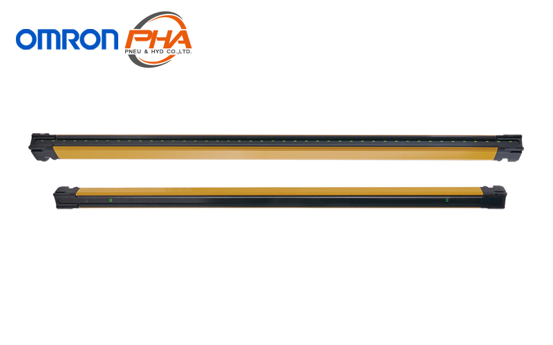
Model Numbers | Safety Light Curtain - F3SG-SR / PG series
F3SG-SR
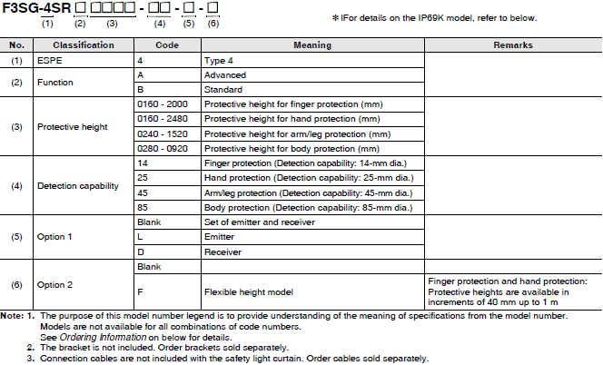
Model Number Legend
Safety Light Curtain F3SG-SR
Ordering Information
Main Units
Safety Light Curtain F3SG-SR
* Emitters and receivers will be available separately.
Example 1) Emitter: F3SG-4SRA0160-14-L, receiver: F3SG-4SRA0160-14-D
Example 2) Receiver (flexible height model) only: F3SG-4SRA0200-14-D-F
Finger protection (Detection capability: 14-mm dia.)
| Number of beams | Protective height (mm) | Advanced | Standard |
|---|---|---|---|
| Model | Model | ||
| 15 | 160 | F3SG-4SRA0160-14 | F3SG-4SRB0160-14 |
| 19 | 200 | F3SG-4SRA0200-14-F | F3SG-4SRB0200-14-F |
| 23 | 240 | F3SG-4SRA0240-14 | F3SG-4SRB0240-14 |
| 27 | 280 | F3SG-4SRA0280-14-F | F3SG-4SRB0280-14-F |
| 31 | 320 | F3SG-4SRA0320-14 | F3SG-4SRB0320-14 |
| 35 | 360 | F3SG-4SRA0360-14-F | F3SG-4SRB0360-14-F |
| 39 | 400 | F3SG-4SRA0400-14 | F3SG-4SRB0400-14 |
| 43 | 440 | F3SG-4SRA0440-14-F | F3SG-4SRB0440-14-F |
| 47 | 480 | F3SG-4SRA0480-14 | F3SG-4SRB0480-14 |
| 51 | 520 | F3SG-4SRA0520-14-F | F3SG-4SRB0520-14-F |
| 55 | 560 | F3SG-4SRA0560-14 | F3SG-4SRB0560-14 |
| 59 | 600 | F3SG-4SRA0600-14-F | F3SG-4SRB0600-14-F |
| 63 | 640 | F3SG-4SRA0640-14 | F3SG-4SRB0640-14 |
| 67 | 680 | F3SG-4SRA0680-14-F | F3SG-4SRB0680-14-F |
| 71 | 720 | F3SG-4SRA0720-14-F | F3SG-4SRB0720-14-F |
| 75 | 760 | F3SG-4SRA0760-14-F | F3SG-4SRB0760-14-F |
| 79 | 800 | F3SG-4SRA0800-14 | F3SG-4SRB0800-14 |
| 83 | 840 | F3SG-4SRA0840-14-F | F3SG-4SRB0840-14-F |
| 87 | 880 | F3SG-4SRA0880-14-F | F3SG-4SRB0880-14-F |
| 91 | 920 | F3SG-4SRA0920-14-F | F3SG-4SRB0920-14-F |
| 95 | 960 | F3SG-4SRA0960-14-F | F3SG-4SRB0960-14-F |
| 99 | 1,000 | F3SG-4SRA1000-14 | F3SG-4SRB1000-14 |
| 119 | 1,200 | F3SG-4SRA1200-14 | F3SG-4SRB1200-14 |
| 139 | 1,400 | F3SG-4SRA1400-14 | F3SG-4SRB1400-14 |
| 159 | 1,600 | F3SG-4SRA1600-14 | F3SG-4SRB1600-14 |
| 179 | 1,800 | F3SG-4SRA1800-14 | F3SG-4SRB1800-14 |
| 199 | 2,000 | F3SG-4SRA2000-14 | F3SG-4SRB2000-14 |
Hand protection (Detection capability: 25-mm dia.)
| Number of beams | Protective height (mm) | Advanced | Standard |
|---|---|---|---|
| Model | Model | ||
| 8 | 160 | F3SG-4SRA0160-25 | F3SG-4SRB0160-25 |
| 10 | 200 | F3SG-4SRA0200-25-F | F3SG-4SRB0200-25-F |
| 12 | 240 | F3SG-4SRA0240-25 | F3SG-4SRB0240-25 |
| 14 | 280 | F3SG-4SRA0280-25-F | F3SG-4SRB0280-25-F |
| 16 | 320 | F3SG-4SRA0320-25 | F3SG-4SRB0320-25 |
| 18 | 360 | F3SG-4SRA0360-25-F | F3SG-4SRB0360-25-F |
| 20 | 400 | F3SG-4SRA0400-25 | F3SG-4SRB0400-25 |
| 22 | 440 | F3SG-4SRA0440-25-F | F3SG-4SRB0440-25-F |
| 24 | 480 | F3SG-4SRA0480-25 | F3SG-4SRB0480-25 |
| 26 | 520 | F3SG-4SRA0520-25-F | F3SG-4SRB0520-25-F |
| 28 | 560 | F3SG-4SRA0560-25 | F3SG-4SRB0560-25 |
| 30 | 600 | F3SG-4SRA0600-25-F | F3SG-4SRB0600-25-F |
| 32 | 640 | F3SG-4SRA0640-25 | F3SG-4SRB0640-25 |
| 34 | 680 | F3SG-4SRA0680-25-F | F3SG-4SRB0680-25-F |
| 36 | 720 | F3SG-4SRA0720-25 | F3SG-4SRB0720-25 |
| 38 | 760 | F3SG-4SRA0760-25-F | F3SG-4SRB0760-25-F |
| 40 | 800 | F3SG-4SRA0800-25 | F3SG-4SRB0800-25 |
| 42 | 840 | F3SG-4SRA0840-25-F | F3SG-4SRB0840-25-F |
| 44 | 880 | F3SG-4SRA0880-25 | F3SG-4SRB0880-25 |
| 46 | 920 | F3SG-4SRA0920-25-F | F3SG-4SRB0920-25-F |
| 48 | 960 | F3SG-4SRA0960-25 | F3SG-4SRB0960-25 |
| 50 | 1,000 | F3SG-4SRA1000-25-F | F3SG-4SRB1000-25-F |
| 52 | 1,040 | F3SG-4SRA1040-25 | F3SG-4SRB1040-25 |
| 56 | 1,120 | F3SG-4SRA1120-25 | F3SG-4SRB1120-25 |
| 60 | 1,200 | F3SG-4SRA1200-25 | F3SG-4SRB1200-25 |
| 64 | 1,280 | F3SG-4SRA1280-25 | F3SG-4SRB1280-25 |
| 68 | 1,360 | F3SG-4SRA1360-25 | F3SG-4SRB1360-25 |
| 72 | 1,440 | F3SG-4SRA1440-25 | F3SG-4SRB1440-25 |
| 76 | 1,520 | F3SG-4SRA1520-25 | F3SG-4SRB1520-25 |
| 80 | 1,600 | F3SG-4SRA1600-25 | F3SG-4SRB1600-25 |
| 84 | 1,680 | F3SG-4SRA1680-25 | F3SG-4SRB1680-25 |
| 88 | 1,760 | F3SG-4SRA1760-25 | F3SG-4SRB1760-25 |
| 92 | 1,840 | F3SG-4SRA1840-25 | F3SG-4SRB1840-25 |
| 96 | 1,920 | F3SG-4SRA1920-25 | F3SG-4SRB1920-25 |
| 104 | 2,080 | F3SG-4SRA2080-25 | F3SG-4SRB2080-25 |
| 114 | 2,280 | F3SG-4SRA2280-25 | F3SG-4SRB2280-25 |
| 124 | 2,480 | F3SG-4SRA2480-25 | F3SG-4SRB2480-25 |
Arm/Leg protection (Detection capability: 45-mm dia.)
| Number of beams | Protective height (mm) | Advanced | Standard |
|---|---|---|---|
| Model | Model | ||
| 6 | 240 | F3SG-4SRA0240-45 | F3SG-4SRB0240-45 |
| 10 | 400 | F3SG-4SRA0400-45 | F3SG-4SRB0400-45 |
| 14 | 560 | F3SG-4SRA0560-45 | F3SG-4SRB0560-45 |
| 18 | 720 | F3SG-4SRA0720-45 | F3SG-4SRB0720-45 |
| 22 | 880 | F3SG-4SRA0880-45 | F3SG-4SRB0880-45 |
| 30 | 1,200 | F3SG-4SRA1200-45 | F3SG-4SRB1200-45 |
| 38 | 1,520 | F3SG-4SRA1520-45 | F3SG-4SRB1520-45 |
Body protection (Detection capability: 85-mm dia.)
| Number of beams | Protective height (mm) | Advanced | Standard |
|---|---|---|---|
| Model | Model | ||
| 4 | 280 | F3SG-4SRA0280-85 | F3SG-4SRB0280-85 |
| 6 | 440 | F3SG-4SRA0440-85 | F3SG-4SRB0440-85 |
| 8 | 600 | F3SG-4SRA0600-85 | F3SG-4SRB0600-85 |
| 10 | 760 | F3SG-4SRA0760-85 | F3SG-4SRB0760-85 |
| 12 | 920 | F3SG-4SRA0920-85 | F3SG-4SRB0920-85 |
F3SG-PG
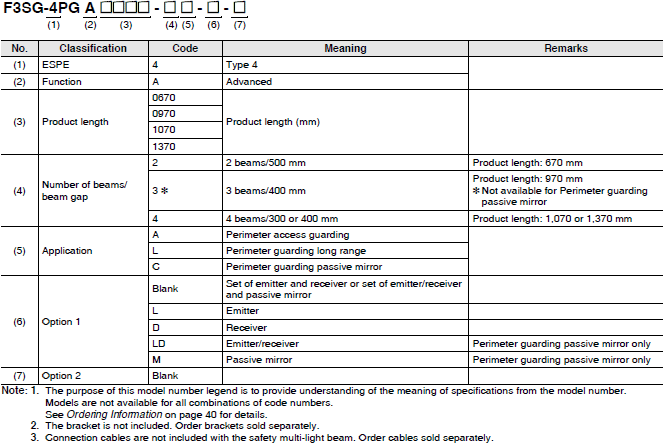
Model Number Legend
Safety Multi-Light Beam F3SG-PG
Ordering Information
Main Units
Safety Multi-Light Beam F3SG-PG
* Emitters and receivers will be available separately.
Example 1) Emitter: F3SG-4PGA0670-2A-L, receiver: F3SG-4PGA0670-2A-D
Example 2) Emitter/receiver: F3SG-4PGA0670-2C-LD, passive mirror: F3SG-4PGA0670-2C-M
Perimeter access guarding (Beam gap: 300 to 500 mm)
| Number of beams | Beam gap (mm) | Product length (mm) | Advanced |
|---|---|---|---|
| Model | |||
| 2 | 500 | 670 | F3SG-4PGA0670-2A |
| 3 | 400 | 970 | F3SG-4PGA0970-3A |
| 4 | 300 | 1,070 | F3SG-4PGA1070-4A |
| 4 | 400 | 1,370 | F3SG-4PGA1370-4A |
Perimeter guarding long range (Beam gap: 300 to 500 mm)
| Number of beams | Beam gap (mm) | Product length (mm) | Advanced |
|---|---|---|---|
| Model | |||
| 2 | 500 | 670 | F3SG-4PGA0670-2L |
| 3 | 400 | 970 | F3SG-4PGA0970-3L |
| 4 | 300 | 1,070 | F3SG-4PGA1070-4L |
| 4 | 400 | 1,370 | F3SG-4PGA1370-4L |
Perimeter guarding passive mirror (Beam gap: 300 to 500 mm)
| Number of beams | Beam gap (mm) | Product length (mm) | Advanced |
|---|---|---|---|
| Model | |||
| 2 | 500 | 670 | F3SG-4PGA0670-2C |
| 4 | 300 | 1,070 | F3SG-4PGA1070-4C |
| 4 | 400 | 1,370 | F3SG-4PGA1370-4C |
F3SG-SR/PG Accessories
(Sold separately)
Bracket Common to F3SG-SR and F3SG-PG
Side mounting and backside mounting are possible.
For fixed mounting
| Application | Appearance | Type | Model |
|---|---|---|---|
| Bracket to mount the F3SG-SR/PG. Side mounting and backside mounting possible. Beam alignment after mounting of F3SG-SR/PG not possible. Two brackets per set (See * below for the number of sets required for each model.) |
 |
Standard Bracket (Intermediate Bracket) |
F39-LSGF |
* Protective height of 0160 to 1440: 2 set (4 brackets), protective height of 1520 to 2480: 3 sets (6 brackets)
The bracket allows beam adjustment after the F3SG-SR/PG is mounted on it.
| Application | Appearance | Type | Model |
|---|---|---|---|
| The angle adjustment range is ±15°. Two brackets per set (See *1 below for the number of sets required for each model.) |
 |
Adjustable Side-Mount Bracket (Intermediate Bracket) |
F39-LSGA |
| Use this bracket at the top and bottom positions of the F3SG-SR/PG. The angle adjustment range is ±22.5°. Use this bracket when replacing an existing F3SJ or F3SN Safety Light Curtain. Two brackets per set (See *2 below for the number of sets required for each model.) |
 |
Adjustable Top/Bottom Bracket F3SJ, F3SN Adapter |
F39-LSGTB-SJ |
| Use this bracket at the top and bottom positions of the F3SG-SR/PG. The angle adjustment range is ±22.5°. Use this bracket when replacing an existing F3SG-RA/ RE Safety Light Curtain. Two brackets per set (See *2 below for the number of sets required for each model.) |
 |
Adjustable Top/Bottom Bracket F3SG-RA/RE Adapter |
F39-LSGTB-RE |
| Use this bracket at the top and bottom positions of the F3SG-SR/PG. The angle adjustment range is ±22.5°. Use this bracket when replacing an existing MS4800 or F3SR Safety Light Curtain. Two brackets per set (See *2 below for the number of sets required for each model.) |
 |
Adjustable Top/Bottom Bracket MS4800, F3SR Adapter |
F39-LSGTB-MS |
*1. Protective height of 0160 to 0280: 1 set (2 brackets), protective height of 0320 to 1440: 2 sets (4 brackets),
protective height of 1520 to 2480: 3 sets (6 brackets)
*2. Using Adjustable Top/Bottom Brackets with Side-Mount Brackets (Intermediate Brackets) or Adjustable Side-Mount
Brackets (Intermediate Brackets)
Protective height of 0840 or less:
The Side-Mount Bracket (Intermediate Bracket) or Adjustable Side-Mount Bracket (Intermediate Bracket) is not
required. Use 2 sets of Adjustable Top/Bottom Brackets.
Protective height of 0880 to 1680:
Use 2 sets of Adjustable Top/Bottom Brackets and 1 set of Side-Mount Brackets (Intermediate Brackets) or Adjustable
Side-Mount Brackets (Intermediate Brackets).
Protective height of 1760 to 2480:
Use 2 sets of Adjustable Top/Bottom Brackets and 2 sets of Side-Mount Brackets (Intermediate Brackets) or Adjustable
Side-Mount Brackets (Intermediate Brackets).
Refer to Dimensions on Catalog and following.
Connecting Cable Common to F3SG-SR and F3SG-PG
[Root Cable]
Root-Straight Cable
| Appearance | Type | Specifications | Cable length | Model |
|---|---|---|---|---|
 |
For emitter To sensors: dedicated connector, To external: open-ended type 5 wires Color: Gray |
 |
3 m | F39-JG3C-L |
| 7 m | F39-JG7C-L | |||
| 10 m | F39-JG10C-L | |||
| For receiver or emitter/receiver of F3SG-PG Perimeter Guarding Passive Mirror To sensors: dedicated connector, To external: open-ended type 8 wires Color: Black |
 |
3 m | F39-JG3C-D | |
| 7 m | F39-JG7C-D | |||
| 10 m | F39-JG10C-D |
Note: Cables are not included with the safety light curtain/safety multi-light beam.
Order the F39-JG[]C-[] Root-Straight Cable or F39-JGR3K-L/-D Root-Plug Cable for Extended.
Root-Plug Cable for Extended
| Appearance | Type | Specifications | Cable length | Model |
|---|---|---|---|---|
 |
For emitter To sensors: dedicated connector, To external: M12 connector type (5-pin) Color: Gray |
 |
0.3 m | F39-JGR3K-L |
| For receiver or emitter/receiver of F3SG-PG Perimeter Guarding Passive Mirror To sensors: dedicated connector, To external: M12 connector type (8-pin) Color: Black |
 |
0.3 m | F39-JGR3K-D |
Note: 1. Cables are not included with the safety light curtain/safety multi-light beam.
Order the F39-JG[]C-[] Root-Straight Cable or F39-JGR3K-L/-D Root-Plug Cable for Extended.
2. Use with the F39-JG[]A-[] Extended Socket-Straight Cable or F39-JG[]B-[] Extended Plug-Socket Cable.
[Extension Cable]
Extended Socket-Straight Cable
| Appearance | Type | Specifications | Cable length | Model |
|---|---|---|---|---|
 |
For emitter M12 connector (5-pin), 5 wires Color: Gray |
 |
3 m | F39-JG3A-L |
| 10 m | F39-JG10A-L | |||
| For receiver or emitter/receiver of F3SG-PG Perimeter Guarding Passive Mirror M12 connector (8-pin), 8 wires Color: Black |
 |
3 m | F39-JG3A-D | |
| 10 m | F39-JG10A-D |
Note: 1. Use with the F39-JGR3K-L/-D Root-Plug Cable for Extended.
2. To extend the cable length to more than 10 m, connect the F39-JG[]B-[] Extended Plug-Socket Cable to the
F39-JG[]A-[] Extended Socket-Straight Cable.
3. Also available in 7, 15 and 20 m. For detail, contact your Omron representative.
Extended Plug-Socket Cable
| Appearance | Type | Specifications | Cable length | Model |
|---|---|---|---|---|
 |
For emitter M12 connector (5-pin) on both ends Color: Gray |
 |
0.5 m | F39-JGR5B-L |
| 1 m | F39-JG1B-L | |||
| 3 m | F39-JG3B-L | |||
| 5 m | F39-JG5B-L | |||
| 7 m | F39-JG7B-L | |||
| 10 m | F39-JG10B-L | |||
| 15 m | F39-JG15B-L | |||
| 20 m | F39-JG20B-L | |||
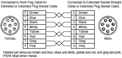
| For receiver or emitter/receiver of F3SG-PG Perimeter Guarding Passive Mirror M12 connector (8-pin) on both ends Color: Black |
 |
0.5 m | F39-JGR5B-D | |
| 1 m | F39-JG1B-D | |||
| 3 m | F39-JG3B-D | |||
| 5 m | F39-JG5B-D | |||
| 7 m | F39-JG7B-D | |||
| 10 m | F39-JG10B-D | |||
| 15 m | F39-JG15B-D | |||
| 20 m | F39-JG20B-D |
* When the accessory is used, protect it from cutting oil.
Note: 1. Use with the F39-JGR3K-L/-D Root-Plug Cable for Extended.
2. To extend the cable length to more than 30 m, connect two or more F39-JG[]B-[] Extended Plug-Socket Cable to the
F39-JG[]A-[] Extended Socket-Straight Cable.
Example: To extend the cable length to 50 m, connect two F39-JG20B-[] (20 m) Extended Plug-Socket Cables and
one F39-JG10A-[] (10 m) Extended Socket-Straight Cable.

Note: 3. Also available in 0.5, 1, 5, 7 and 15 m. For detail, contact your Omron representative.
[Cascading Cable]
Side-by-side Cascading Cable (Two cables per set, one for emitter and one for receiver)
| Appearance | Type | Specifications | Cable length | Model |
|---|---|---|---|---|
 |
For emitter To sensors: dedicated connector 1, To cascading sensors: dedicated connector 2 Color: Gray For receiver To sensors: dedicated connector 1, To cascading sensors: dedicated connector 2 Color: Black |
Used to series-connect sensors with the minimum cable length of 12 cm. IP67 and IP67G (JIS C 0920 Annex 1) rated when mated. |
12 cm | F39-JGR12L |
Cascading Cable for Extended.
Cascading Cable for Extended (Two cables per set, one for emitter and one for receiver)
| Appearance | Type | Specifications | Cable length | Model |
|---|---|---|---|---|
 |
For emitter To sensors: dedicated connector, To cascading sensors: M12 connector type (5 pin) Color: Gray For receiver To sensors: dedicated connector, To cascading sensors: M12 connector type (8 pin) Color: Black |
Used together with the F39- JGR3K Root-Plug Cable for Extended to extend the cable length between the series- connected sensors to more than 12 cm. IP67 and IP67G (JIS C 0920 Annex 1) rated when mated. |
0.3 m | F39-JGR3W |
Extended Plug-Socket Cable (up to 10 m: F39-JG10B-[]) to the F39-JGR3W Cascading Cable for Extended.
Extension cable between sensors: 10 m max. (not including Cascading Cable for Extended (F39-JGR3W) and
Root Cable (F39-JGR3K-L/-D).)

[Conversion Cable: Converting Wiring for Existing Light Curtain]
Conversion Cable
| Appearance | Specifications | Type | Cable length | Model |
|---|---|---|---|---|
 |
Used to convert the wiring for F3SJ-B/-A, F3SR-B or F3SN Safety Light Curtain to that for the F3SG-SR. |
F3SJ-B/A Conversion Cable For emitter To sensor: dedicated connector 1, To wires for F3SJ-B/-A, F3SR or F3SN: M12 connector type (8 pin) Color: Gray |
0.3 m | F39-JGR3K-SJ-L |
| F3SJ-B/A Conversion Cable For receiver To sensor: dedicated connector 1, To wires for F3SJ-B/-A, F3SR or F3SN: M12 connector type (8 pin) Color: Black |
F39-JGR3K-SJ-D | |||
| Used to convert the wiring for F3SG-RE Safety Light Curtain to that for the F3SG-SR. |
F3SG-RE Conversion Cable For emitter To sensor: dedicated connector 1, To wires for F3SG-RE: M12 connector type (4 pin) Color: Gray |
0.3 m | F39-JGR3K-RE-L | |
| F3SG-RE Conversion Cable For receiver To sensor: dedicated connector 1, To wires for F3SG-RE: M12 connector type (4 pin) Color: Black |
F39-JGR3K-RE-D | |||
| Used to convert the wiring for MS4800 Safety Light Curtain to that for the F3SG-SR. |
MS48 Conversion Cable For emitter To sensor: dedicated connector 1, To wires for MS4800: M12 connector type (5 pin) Color: Gray |
0.3 m | F39-JGR3K-MS-L | |
| MS48 Conversion Cable For receiver To sensor: dedicated connector 1, To wires for MS4800: M12 connector type (8 pin) Color: Black |
F39-JGR3K-MS-D |
When connecting to the cables of the existing light curtain, order the conversion cables.
Conversion cables are only for PNP connection. To use for NPN, connect the 24 VDC line and the 0 VDC line in
reverse. For details, refer to User's Manual (Man. No. Z405).
 Note: 2. Do not connect the Conversion Cable for the following purposes. Failure to do so may result in failure.
 1. Connecting with the F39-SGIT-IL3, F39-GCNY2, F39-GCNY3 or F39-GCN5
2. Connecting between the F3SG-SR's
Configuration Tool SD Manager 3 and Intelligent Tap
Configuration tool SD Manager 3
| Type | Specifications |
|---|---|
| SD Manager 3 | Configuration tool running on a PC. Use with the Intelligent Tap. (The Bluetooth® communication unit is required to connect using Bluetooth®.) For details, refer to your local Omron website. |
| SD Manager 3 Mobile APP | Monitoring tool running on a smartphone. Use with the Intelligent Tap and Bluetooth® communication unit. For details, refer to your local Omron website. |
Intelligent Tap *
| Appearance | Specifications | Type | Model |
|---|---|---|---|
 |
Used to configure the F3SG-SR/PG and connect external devices via IO-Link. The F3SG-SR/PG can be configured on a PC or with the DIP switch on the Intelligent Tap. IP67 and IP67G (JIS C 0920 Annex 1) rated when mated. |
Intelligent Tap | F39-SGIT-IL3 |
 |
Mounted to the Intelligent Tap to connect with the SD Manager 3 via Bluetooth®. IP67 and IP67G (JIS C 0920 Annex 1) rated when mated. * For the regions where the Bluetooth® Communication Unit can be used, refer to Legislation and Standards on Catalog. |
Bluetooth® Communication Unit | F39-SGBT |
 |
Bracket to mount the Intelligent Tap on a DIN track. |
Intelligent Tap Bracket For DIN in Panel | F39-LITF1 |
Note: Please contact your OMRON sales representative regarding the IO-Link setup file (IODD file).
* Use the F39-SGBT Bluetooth® Communication Unit or a commercially available USB Type-C™ cable to connect to a PC.
Intelligent Tap-to-IO-Link Master Cable
| Omron IO-Link master unit | Type | Specifications | Cable length | Model |
|---|---|---|---|---|
| NX-ILM400 | Single-ended cable M12 connector (5-pin), 5 wires Color: Gray |
 |
2 m | XS5F-D521-DJ0-IL |
| GX-ILM08C | Double-ended cable M12 connector (5-pin), 5 wires Color: Gray |
 |
3 m | F39-JG3B-L |
| 10 m | F39-JG10B-L | |||
| 20 m | F39-JG20B-L |
Note: Use the F39-JG[]A-D Extended Socket-Straight Cable or F39-JG[]B-D Extended Plug-Socket Cable for safety output
(OSSD).

Reduced Wiring System
Y-Joint Plug/Socket Connector
| Appearance | Type | Specifications | Cable length | Model |
|---|---|---|---|---|
 |
M12 connectors. Used for reduced wiring. IP67*1 rated when mated. |
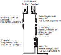 |
0.5 m | F39-GCNY2 |
*2. Order the cable (root-plug cable for extended and extended cable) for emitter (end of model: -L) and the cable for
receiver (end of model: -D).
Reset Switch Connector
| Appearance | Type | Specifications | Cable length | Model |
|---|---|---|---|---|
 |
M12 connectors. Used for reduced wiring. IP67*1 rated when mated. |
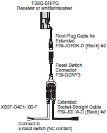 |
0.5 m | F39-GCNY3 |
Note: Purchase a reset switch (NC contact) separately.
*1. When the accessory is used, protect it from cutting oil.
*2. Order the extended socket-straight cable for receiver (end of model: -D).
*3. The External Device Monitoring (EDM) function cannot be used with this accessory.
Reset Switch Connector-to-Reset Switch Cable
Connector Connected to Cable, Socket on One Cable End
| Appearance | Type | Specifications | Cable length | Model |
|---|---|---|---|---|
 |
M12 connector (4-pin), 4 wires |
 |
1 m | XS5F-D421-C80-F |
| 2 m | XS5F-D421-D80-F | |||
| 3 m | XS5F-D421-E80-F | |||
| 5 m | XS5F-D421-G80-F | |||
| 10 m | XS5F-D421-J80-F | |||
| 20 m | XS5F-D421-L80-F |
* When the accessory is used, protect it from cutting oil.
Muting System
Muting Sensor E3Z (M8 Connector)
| Sensing method | Sensing distance | Mounter | Output type | Model |
|---|---|---|---|---|
Through-beam  |
10 m (Red light) |
F39-FMA[][][]T | NPN output | E3Z-T66A |
| PNP output | E3Z-T86A | |||
Retro-reflective *1  |
4 m *2 (Red light) |
F39-FMA[][][]R | NPN output | E3Z-R66 |
| PNP output | E3Z-R86 | |||
| Reflectors | E39-R1S |
*1. The reflector is not included with the muting sensor. Order the E39-R1S Reflector when using the E3Z-R[]6
Retroreflective Muting Sensor.
*2. The minimum required distance between the E3Z Muting Sensor and reflector is 100 mm.
For details, refer to your local Omron website.
Muting Sensor Arm Mounter (Two mounters per set, for emitter and receiver)
| Appearance | Application | Length | Model |
|---|---|---|---|
 |
The through-beam muting sensor can be mounted easily. | 150 mm | F39-FMA150T |
| 400 mm | F39-FMA400T | ||
| The retroreflective muting sensor can be mounted easily. | 150 mm | F39-FMA150R | |
| 400 mm | F39-FMA400R |
Note: 1. The muting sensor is not included with the muting sensor arm mounter. Order the Muting Sensor.
2. When mounting the muting sensor arm mounter to the safety light curtain, order the F39-LMAF1 Muting Sensor
Arm Mounter Bracket for SLC. When the muting sensor arm mounter is mounted to the floor mount column, no
brackets are required.
Muting Sensor Arm Mounter Bracket for SLC (Two brackets per set, for emitter and receiver) *
| Appearance | Application | Model |
|---|---|---|
 |
For F3SG-SR/PG | F39-LMAF1 |
length smaller than 280 mm.
* Order when mounting the muting sensor arm mounter to the safety light curtain. When the muting sensor arm mounter
is mounted to the floor mount column, no brackets are required.
Muting Sensor Connection Box
| Appearance | Application | Specifications | Cable Length | Model |
|---|---|---|---|---|
 |
Speeds up wiring muting sensors. | PNP/NPN selection Main Unit: M12 socket (5 pin) ×7, M12 socket (8 pin) ×1 Cable: M12 plug (8 pin) ×1 IP67*1 rated when mated. |
0.5 m | F39-GCN5 |
*1. When the accessory is used, protect it from cutting oil.
*2. When using four muting sensors, order the E3Z-R[][] Muting Sensor (Retro-reflective) that can be connected to the
F39-GCN5 Muting Sensor Connection Box.
Connection Cable for Muting Sensor Connection Box
| Appearance | Application | Specifications | Cable Length | Model |
|---|---|---|---|---|
 |
Cable to connect the Muting Sensor and F39-GCN5 Muting Sensor Connection Box. |
Connectors connected to cable, M8 socket and M12 plug on cable ends (4 pin) |
0.2 m | XS3W-M42C-4C2-A |
 |
Sensor I/O Connectors Connectors with Cables, Connectors on Both Cable Ends (Socket/Plug) |
Connectors connected to cable, M8 socket and M8 plug on cable ends (4 pin) Straight (socket, plug) |
1 m | XS3W-M421-401-R |
| 2 m | XS3W-M421-402-R | |||
| 5 m | XS3W-M421-405-R | |||
| 10 m | XS3W-M421-410-R | |||
 |
Sensor I/O Connectors Connectors with Cables, Connectors on Both Cable Ends (Socket/Plug) Used together with the XS3W- M42C-4C2-A when the space to connect to the connector of the E3Z Muting Sensor is between 40 and 80 mm. |
Connectors connected to cable, M8 socket and M8 plug on cable ends (4 pin) Right-angle (socket)/ straight (plug) |
2 m | XS3W-M424-402-R |
| 5 m | XS3W-M424-405-R | |||
 |
Cable to connect the device for auxiliary output and F39-GCN5 Muting Sensor Connection Box |
Connector connected to cable, M12 plug on one cable end (4 pin) |
0.3 m | XS5H-D421-A80-F |
| 1 m | XS5H-D421-C80-F | |||
| 2 m | XS5H-D421-D80-F | |||
| 5 m | XS5H-D421-G80-F | |||
 |
Cable to connect the device for reset input and F39-GCN5 Muting Sensor Connection Box |
Connector connected to cable, M12 plug on one cable end (5 pin) |
0.3 m | XS2H-D521-AG0-A |
| 1 m | XS2H-D521-CG0-A |
Note: 1. Select the same output type for both the safety light curtain/safety multi-light beam (PNP/NPN selection by wiring)
and muting sensor (PNP or NPN model).
2. For details of the XS3W, XS5H and XS2H cables with connector(s), refer to your local OMRON website.
3. Use the F39-JG[]B-D Extended Plug-Socket Cable to connect the muting sensor connection box with the Intelligent
Tap.
The connection example for optical synchronization is shown below.
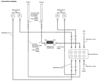
Floor Mount System
Floor Mount Column
| Appearance | Applicable light curtain | Column height | Model | |
|---|---|---|---|---|
| F3SG-SR Safety Light Curtain | F3SG-PG Safety Multi-Light Beam | |||
 |
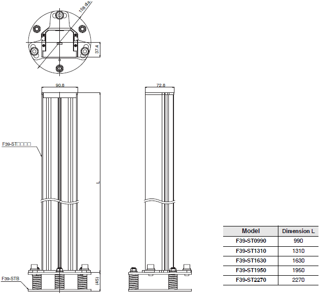
Protective height up to 0880 | F3SG-4PGA0670-2[] | 990 mm | F39-ST0990 |
| Protective height up to 1280 | F3SG-4PGA0970-3A/3L F3SG-4PGA1070-4[] |
1,310 mm | F39-ST1310 | |
| Protective height up to 1520 | F3SG-4PGA1370-4[] | 1,630 mm | F39-ST1630 | |
| Protective height up to 1840 | --- | 1,950 mm | F39-ST1950 | |
| Protective height up to 2080 | --- | 2,270 mm | F39-ST2270 | |
*1. Floor Mount Column, Mirror Column, Mount-Column Adjustable Base: Each model includes one product.
When using for both the emitter and receiver, order two sets.
*2. The mount-column adjustable base is sold separately.
Mirror Column
| Appearance | Applicable light curtain | Column height | Model | |
|---|---|---|---|---|
| F3SG-SR Safety Light Curtain | F3SG-PG Safety Multi-Light Beam | |||
 (Operating range becomes 15% shorter than the rating) |
Protective height up to 0880 | F3SG-4PGA0670-2A/2L | 990 mm | F39-SML0990 |
| Protective height up to 1200 | F3SG-4PGA0970-3A/3L F3SG-4PGA1070-4A/4L |
1,310 mm | F39-SML1310 | |
| Protective height up to 1520 | F3SG-4PGA1370-4A/4L | 1,630 mm | F39-SML1630 | |
| Protective height up to 1840 | --- | 1,950 mm | F39-SML1950 | |
 (Operating range becomes 10% shorter than the rating) |
--- | F3SG-4PGA0670-2A/2L | 990 mm | F39-PML0990-2 |
| --- | F3SG-4PGA0970-3A/3L | 1,310 mm | F39-PML1310-3 | |
| --- | F3SG-4PGA1070-4A/4L | F39-PML1310-4 | ||
| --- | F3SG-4PGA1370-4A/4L | 1,630 mm | F39-PML1630-4 | |
Note: The F3SG-SR Safety Light Curtain with the protective height of 1920 or more cannot be used.
*1. Floor Mount Column, Mirror Column, Mount-Column Adjustable Base: Each model includes one product.
When using for both the emitter and receiver, order two sets.
*2. The mount-column adjustable base is sold separately.
Mount-Column Adjustable Base
| Appearance | Application | Model |
|---|---|---|
 |
Mounted to the floor mount column or mirror column. The angle and height of the column can be adjusted. |
F39-STB |
*1. Floor Mount Column, Mirror Column, Mount-Column Adjustable Base: Each model includes one product.
When using for both the emitter and receiver, order two sets.
*2. The floor mount column and mirror column are sold separately.
Other Optional Accessories Common to F3SG-SR and F3SG-PG
Laser Alignment Pointer
| Appearance | Specifications | Model |
|---|---|---|
 |
The laser alignment pointer is attached on the optical surface of the F3SG-SR/PG to help coarse adjustment of beams. |
F39-PTG |
Lamp
| Appearance | Specifications | Model |
|---|---|---|
 |
The lamp can be connected to emitter, receiver, or emitter/receiver and turned ON based on the operation of F3SG-SR/PG. The lamp can indicate red, orange, and green colors, to which three different states can be assigned. IP67 * rated when mated. |
F39-SGLP |
* When the accessory is used, protect it from cutting oil.
Note: The Lamp does not support Bluetooth® communication.
Optional Accessories for F3SG-SR (Note: Cannot be used on F3SG-PG.)
Spatter Protection Cover (2 covers per set, one for emitter and one for receiver)
| Appearance | Safety light curtain | Model | ||
|---|---|---|---|---|
| Finger protection | Hand protection | Arm/leg protection | ||
 (Operating range becomes 10% shorter than the rating) |
F3SG-4SR[]0160-14 | F3SG-4SR[]0160-25 | --- | F39-HSG0160 |
| F3SG-4SR[]0240-14 | F3SG-4SR[]0240-25 | F3SG-4SR[]0240-45 | F39-HSG0240 | |
| F3SG-4SR[]0320-14 | F3SG-4SR[]0320-25 | --- | F39-HSG0320 | |
| F3SG-4SR[]0400-14 | F3SG-4SR[]0400-25 | F3SG-4SR[]0400-45 | F39-HSG0400 | |
| F3SG-4SR[]0480-14 | F3SG-4SR[]0480-25 | --- | F39-HSG0480 | |
| F3SG-4SR[]0560-14 | F3SG-4SR[]0560-25 | F3SG-4SR[]0560-45 | F39-HSG0560 | |
| F3SG-4SR[]0640-14 | F3SG-4SR[]0640-25 | --- | F39-HSG0640 | |
| --- | F3SG-4SR[]0720-25 | F3SG-4SR[]0720-45 | F39-HSG0720 | |
| F3SG-4SR[]0800-14 | F3SG-4SR[]0800-25 | --- | F39-HSG0800 | |
| --- | F3SG-4SR[]0880-25 | F3SG-4SR[]0880-45 | F39-HSG0880 | |
| F3SG-4SR[]0960-14-F | F3SG-4SR[]0960-25 | --- | F39-HSG0960 | |
| --- | F3SG-4SR[]1040-25 | --- | F39-HSG1040 | |
| --- | F3SG-4SR[]1120-25 | --- | F39-HSG1120 | |
| F3SG-4SR[]1200-14 | F3SG-4SR[]1200-25 | F3SG-4SR[]1200-45 | F39-HSG1200 | |
| --- | F3SG-4SR[]1280-25 | --- | F39-HSG1280 | |
| --- | F3SG-4SR[]1360-25 | --- | F39-HSG1360 | |
| --- | F3SG-4SR[]1440-25 | --- | F39-HSG1440 | |
| --- | F3SG-4SR[]1520-25 | F3SG-4SR[]1520-45 | F39-HSG1520 | |
| F3SG-4SR[]1600-14 | F3SG-4SR[]1600-25 | --- | F39-HSG1600 | |
| --- | F3SG-4SR[]1680-25 | --- | F39-HSG1680 | |
| --- | F3SG-4SR[]1760-25 | --- | F39-HSG1760 | |
| --- | F3SG-4SR[]1840-25 | --- | F39-HSG1840 | |
| --- | F3SG-4SR[]1920-25 | --- | F39-HSG1920 | |
above.
The F39-HSG0360 is also available for use together with other spatter protection covers.
Test Rod *
| Appearance | Diameter | Model |
|---|---|---|
| --- | 14 mm | F39-TRD14 |
| 25 mm | F39-TRD25 | |
| 30 mm | F39-TRD30 |
* When you need a test rod larger than 30 mm in diameter, prepare it by yourself.
F3SG-SR-K
Model Number Legend
IP69K Model F3SG-SR-K
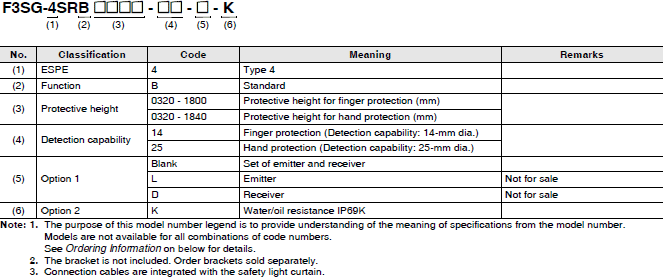
Ordering Information
Safety Light Curtain IP69K Model
Main Unit F3SG-SR-K
Finger protection (Detection capability: 14-mm dia.)
| Number of beams | Protective height (mm) | Standard |
|---|---|---|
| Model | ||
| 31 | 320 | F3SG-4SRB0320-14-K |
| 39 | 400 | F3SG-4SRB0400-14-K |
| 47 | 480 | F3SG-4SRB0480-14-K |
| 55 | 560 | F3SG-4SRB0560-14-K |
| 63 | 640 | F3SG-4SRB0640-14-K |
| 71 | 720 | F3SG-4SRB0720-14-K |
| 79 | 800 | F3SG-4SRB0800-14-K |
| 87 | 880 | F3SG-4SRB0880-14-K |
| 95 | 960 | F3SG-4SRB0960-14-K |
| 99 | 1,000 | F3SG-4SRB1000-14-K |
| 119 | 1,200 | F3SG-4SRB1200-14-K |
| 139 | 1,400 | F3SG-4SRB1400-14-K |
| 159 | 1,600 | F3SG-4SRB1600-14-K |
| 179 | 1,800 | F3SG-4SRB1800-14-K |
Note: Connection cables are integrated with the safety light curtain.
Hand protection (Detection capability: 25-mm dia.)
| Number of beams | Protective height (mm) | Standard |
|---|---|---|
| Model | ||
| 16 | 320 | F3SG-4SRB0320-25-K |
| 20 | 400 | F3SG-4SRB0400-25-K |
| 24 | 480 | F3SG-4SRB0480-25-K |
| 28 | 560 | F3SG-4SRB0560-25-K |
| 32 | 640 | F3SG-4SRB0640-25-K |
| 36 | 720 | F3SG-4SRB0720-25-K |
| 40 | 800 | F3SG-4SRB0800-25-K |
| 44 | 880 | F3SG-4SRB0880-25-K |
| 48 | 960 | F3SG-4SRB0960-25-K |
| 50 | 1,000 | F3SG-4SRB1000-25-K |
| 52 | 1,040 | F3SG-4SRB1040-25-K |
| 56 | 1,120 | F3SG-4SRB1120-25-K |
| 60 | 1,200 | F3SG-4SRB1200-25-K |
| 64 | 1,280 | F3SG-4SRB1280-25-K |
| 68 | 1,360 | F3SG-4SRB1360-25-K |
| 72 | 1,440 | F3SG-4SRB1440-25-K |
| 76 | 1,520 | F3SG-4SRB1520-25-K |
| 80 | 1,600 | F3SG-4SRB1600-25-K |
| 84 | 1,680 | F3SG-4SRB1680-25-K |
| 88 | 1,760 | F3SG-4SRB1760-25-K |
| 92 | 1,840 | F3SG-4SRB1840-25-K |
Note: Connection cables are integrated with the safety light curtain.
Accessories (Sold separately)
Optional Accessories for F3SG-SR-K
Bracket
| Appearance | Type | Application | Model |
|---|---|---|---|
| Bracket to mount the F3SG-SR-K. 360° mounting including side mounting and backside mounting possible. Beam alignment after mounting of F3SG-SR/PG not possible. Two brackets per set |
 |
IP69K Model Mounting Bracket (Top/Bottom Bracket) |
F39-LSGTB-K |
Specifications | Safety Light Curtain - F3SG-SR / PG series
Safety Light Curtain/Safety Multi-Light Beam
F3SG-SR Main Unit
[][][][] in the model number indicates the protective height or product length in millimeters.
| Model | Safety Light Curtain | ||||||
|---|---|---|---|---|---|---|---|
| F3SG- []SRA[][][][] -14 F3SG- []SRB[][][][] -14 | F3SG- []SRA[][][][] -25 F3SG- []SRB[][][][] -25 | F3SG- []SRA[][][][] -45 F3SG- []SRB[][][][] -45 | F3SG- []SRA[][][][] -85 F3SG- []SRB[][][][] -85 | ||||
| Perfor- mance | Object resolution (Detection capability) |
Opaque objects | |||||
| 14-mm dia. | 25-mm dia. | 45-mm dia. | 85-mm dia. | ||||
| Beam gap | 10 mm | 20 mm | 40 mm | 80 mm | |||
| Number of beams | 15 to 199 | 8 to 124 | 6 to 38 | 4 to 12 | |||
| Lens size | 4.4 × 3.4 mm (W × H) |
6.7 × 4.5 mm (W × H) | |||||
| Protective height | 160 to 2,000 mm |
160 to 2,480 mm |
240 to 1,520 mm |
280 to 920 mm | |||
| Product length | --- | ||||||
| Operating range | Long | 0.3 to 10.0 m (Typ. 15.0 m) * |
0.3 to 20.0 m (Typ. 30.0 m) | ||||
| Short | 0.3 to 3.0 m (Typ. 4.5 m) * |
0.3 to 7.0 m (Typ.10.5 m) | |||||
| * When operating at an ambient temperature of -10 to -30°C, use the F3SG-SR with the operating range of 0.3 to 5.0 m in Long Mode and 0.3 to 1.5 m in Short Mode. |
|||||||
| Response time *1 | Normal mode | ON to OFF | Optical synchronization: 8 to 18 ms Wired synchronization: 10 to 21 ms |
Optical synchronization: 8 to 13 ms Wired synchronization: 10 to 17 ms |
Optical synchronization: 8 ms Wired synchronization: 10 ms |
||
| OFF to ON | Optical synchronization: 40 to 90 ms Wired synchronization: 50 to 105 ms |
Optical synchronization: 40 to 65 ms Wired synchronization: 50 to 85 ms |
Optical synchronization: 40 ms Wired synchronization: 50 ms |
||||
| ×2 Slow mode *2 | ON to OFF | Optical synchronization: 16 to 36 ms Wired synchronization: 20 to 42 ms |
Optical synchronization: 16 to 26 ms Wired synchronization: 20 to 34 ms |
Optical synchronization: 16 ms Wired synchronization: 20 ms |
|||
| OFF to ON | Optical synchronization: 80 to 180 ms Wired synchronization: 100 to 210 ms |
Optical synchronization: 80 to 130 ms Wired synchronization: 100 to 170 ms |
Optical synchronization: 80 ms Wired synchronization: 100 ms |
||||
| ×4 Slow mode *2 | ON to OFF | Optical synchronization: 32 to 72 ms Wired synchronization: 40 to 84 ms |
Optical synchronization: 32 to 52 ms Wired synchronization: 40 to 68 ms |
Optical synchronization: 32 ms Wired synchronization: 40 ms |
|||
| OFF to ON | Optical synchronization: 160 to 360 ms Wired synchronization: 200 to 420 ms |
Optical synchronization: 160 to 260 ms Wired synchronization: 200 to 340 ms |
Optical synchronization: 160 ms Wired synchronization: 200 ms |
||||
| ×8 Slow mode *2 | ON to OFF | Optical synchronization: 64 to 144 ms Wired synchronization: 80 to 168 ms |
Optical synchronization: 64 to 104 ms Wired synchronization: 80 to 136 ms |
Optical synchronization: 64 ms Wired synchronization: 80 ms |
|||
| OFF to ON | Optical synchronization: 320 to 720 ms Wired synchronization: 400 to 840 ms |
Optical synchronization: 320 to 520 ms Wired synchronization: 400 to 680 ms |
Optical synchronization: 320 ms Wired synchronization: 400 ms |
||||
| *1. Response time when used in one segment system. Refer to Catalog. Refer to the User's Manual (Man. No. Z405) for cascaded connection. *2. Selectable by SD Manager 3. |
|||||||
| Effective aperture angle (EAA) (IEC 61496-2) |
±2.5° max. * Emitter and receiver at operating range of 3 m or greater. |
||||||
| Light source | Infrared LEDs, Wavelength: 870 nm | ||||||
| Startup waiting time | 3 s max. | ||||||
| Elec- trical | Power supply voltage (Vs) | SELV/PELV 24 VDC±20% (ripple p-p 10% max.) | |||||
| Current consumption | Refer to Catalog. | ||||||
| Safety outputs (OSSD) | Two PNP or NPN transistor outputs (PNP or NPN is selectable by wiring of power supply.) Load current: 300 mA max., Residual voltage: 2 V max. (except for voltage drop due to cable extension), Capacitive load: 1 μF max., Inductive load: 2.2 H max. *1*2*3 Leakage current: 1 mA max. (PNP), 2 mA max. (NPN) *4 *1. For the F3SG-4SRA, the load current is 150 mA max. in 2- segment cascade and 80 mA max. in 3-segment cascade. *2. The residual voltage is 3 V max. when the Intelligent Tap is connected to the sensor. *3. The load inductance is the maximum value when the safety output frequently repeats ON and OFF. When you use the safety output at 4 Hz or less, the usable load inductance becomes larger. *4. These values must be taken into consideration when connecting elements including a capacitive load such as a capacitor. |
||||||
| Auxiliary output | Two PNP or NPN transistor 1 outputs (PNP or NPN is selectable by wiring of power supply.) Load current: 100 mA max., Residual voltage: 2 V max. * * The residual voltage is 3 V max. when the Intelligent Tap is connected to the sensor. |
||||||
| Output operation mode | Safety output | Light-ON (Safety outputs are turned to the ON state when the receiver receives an emitting signal.) |
|||||
| Auxiliary output | Safety output (Inverted signal output: Enable) (default) (Configurable by SD Manager 3) |
||||||
| Input voltage | TEST | Light emission stops when connected to 24 VDC ON voltage: Vs-3 V to Vs (short circuit current: approx. 5.0 mA) * OFF voltage: 0 V to 1/2 Vs, or open (short circuit current: approx. 6.0 mA) * Light emission stops when connected to 0 V ON voltage: 0 to 3 V (short circuit current: approx. 6.0 mA) OFF voltage: 1/2 Vs to Vs, or open (short circuit current: approx. 5.0 mA) * |
|||||
| OPERATING RANGE SELECT INPUT |
Long: 12 V to Vs (short circuit current: approx. 4.2 mA) * or open Short: 0 to 3 V (short circuit current: approx. 4.2 mA) |
||||||
| RESET/EDM | PNP ON voltage: Vs-3 V to Vs (short circuit current: approx. 9.5 mA) * OFF voltage: 0 V to 1/2 Vs, or open (short circuit current: approx. 13.0 mA) * NPN ON voltage: 0 to 3 V (short circuit current: approx. 13.0 mA) OFF voltage: 1/2 Vs to Vs, or open (short circuit current: approx. 9.5 mA) * |
||||||
| MUTE A/B, RE-RESET, PSDI |
PNP ON voltage: Vs-3 V to Vs (short circuit current: approx. 4.5 mA) * OFF voltage: 0 V to 1/2 Vs, or open (short circuit current: approx. 7.0 mA) * NPN ON voltage: 0 to 3 V (short circuit current: approx. 7.0 mA) OFF voltage: 1/2 Vs to Vs, or open (short circuit current: approx. 4.5 mA) * |
||||||
| * The Vs indicates a supply voltage value in your environment. | |||||||
| Overvoltage category (IEC 60664-1) | II | ||||||
| Indicators | Refer to Catalog. | ||||||
| Protective circuit | Output short-circuit protection | ||||||
| Insulation resistance | 20 M or higher (500 VDC megger) | ||||||
| Dielectric strength | 1,000 VAC, 50/60 Hz (1 min) | ||||||
| Func- tional | Mutual interference prevention | Optical synchronization by Scan Code: in up to 2 sets Wired synchronization: in up to 3 sets |
|||||
| Cascade connection | Number of cascaded segments: 3 max. Total number of beams: 255 max. |
||||||
| Test function | Self-test (at power-on, and during operation) External test (light emission stop function by test input) |
||||||
| Safety-related functions | Interlock External Device Monitoring (EDM) Pre-Reset PSDI Fixed Blanking/Floating Blanking Reduced Resolution Muting/Override Mutual Interference Prevention PNP/NPN Selection Response Time Adjustment |
||||||
| Environ- mental | Ambient temperature | Operating | -30 to 55 °C (non-icing) | ||||
| Storage | -30 to 70 °C | ||||||
| Ambient humidity | Operating | 35% to 85% (non-condensing) | |||||
| Storage | 35% to 95% | ||||||
| Ambient illuminance | Incandescent lamp: 3,000 Ix max. on receiver surface Sunlight: 10,000 Ix max. on receiver surface |
||||||
| Degree of protection (IEC 60529) | IEC 60529: IP65 and IP67, JIS C 0920 Annex 1: IP67G | ||||||
| Vibration resistance (IEC 61496-1) | 10 to 55 Hz, Multiple amplitude of 0.7 mm, 20 sweeps for all 3 axes | ||||||
| Shock resistance (IEC 61496-1) | 100 m/s2, 1000 shocks for all 3 axes | ||||||
| Pollution degree (IEC 60664-1) | 3 | ||||||
| Connec- tions | Root cable | Type of connection | To sensors: dedicated connector, To external: M12 connector type (5-pin emitter and 8-pin receiver) or open-ended type IP67 and IP67G (JIS C 0920 Annex 1) * rated when mated. * The F3SG-SR meets the degree of protection when the root cable is correctly connected with the F3SG-SR. The degree of protection is not satisfied with the part where cable wires are uncovered. |
||||
| Number of wires | Emitter: 5, Receiver: 8 | ||||||
| Cable length | Refer to Catalog | ||||||
| Cable diameter | 6 mm | ||||||
| Minimum bending radius |
R5 mm | ||||||
| Cascading cable | Type of connection | To sensors: dedicated connector, To cascading sensors: M12 connector type (5-pin emitter and 8-pin receiver) or dedicated connector IP67 and IP67G (JIS C 0920 Annex 1) * rated when mated. * The F3SG-SR meets the degree of protection when the cascading cable is correctly connected with the F3SG-SR and the root cable. The degree of protection is not satisfied with the part where cable wires are uncovered. |
|||||
| Number of wires | Emitter: 5, Receiver: 8 | ||||||
| Cable length | Refer to Catalog | ||||||
| Cable diameter | 6 mm | ||||||
| Minimum bending radius |
R5 mm | ||||||
| Extension cable - Extended Socket- Straight Cable - Extended Plug-Socket Cable | Type of connection | M12 connector type (5-pin emitter and 8-pin receiver), IP67 * rated when mated * The extension cable meets the degree of protection when the root cable is correctly connected with the extension cable. The degree of protection is not satisfied with the part where cable wires are uncovered. |
|||||
| Number of wires | Emitter: 5, Receiver: 8 | ||||||
| Cable length | Refer to Catalog | ||||||
| Cable diameter | 6.6 mm | ||||||
| Minimum bending radius |
R36 mm | ||||||
| Cable extension |
Refer to Catalog for restrictions on cable extension. | ||||||
| Root cable | In optical synchronization: 100 m max. * between power supply and emitter and between power supply and receiver In wired synchronization: 100 m max. * between power supply and emitter, between power supply and receiver, and between emitter and receiver * When the Intelligent Tap (F39-SGIT-IL3) is connected to the sensor, this applies in the case of the rated power supply of 24 VDC to 24 VDC +20%. |
||||||
| Cascade connection | Extension cable between sensors: 10 m max. (not including Cascading Cable for Extended *1 and Root Cable *2.) *1. F39-JGR3W *2. F39-JGR3K |
||||||
| Material | Housing: Aluminum alloy Cap: PBT resin Front window: Acrylic resin FE plate: Stainless steel |
||||||
| Weight | Refer to Catalog. | ||||||
| Included accessories | Instruction Sheet, Quick Installation Manual, Troubleshooting Guide Sticker, Warning Zone Label End Cap (for switching Scan Code Selection function) |
||||||
| Con- formity | Conforming standards | Refer to Catalog. | |||||
| Type of ESPE (IEC 61496-1) | Type 4 | ||||||
| Performance Level (PL)/ Safety category |
PL e/Category 4 (EN ISO 13849-1:2015) | ||||||
| PFHD | 1.1× 10⁻⁸ max. (IEC 61508) | ||||||
| Proof test interval TM | Every 20 years (IEC 61508) | ||||||
| SFF | 99% (IEC 61508) | ||||||
| HFT | 1 (IEC 61508) | ||||||
| Classification | Type B (IEC 61508-2) | ||||||
F3SG-PG Main Unit
[][][][] in the model number indicates the protective height or product length in millimeters.
| Model | Safety Multi-Light Beam | |||||
|---|---|---|---|---|---|---|
| F3SG- 4PGA[][][][] -[]A | F3SG- 4PGA[][][][]-[]L | F3SG- 4PGA[][][][]-[]C | ||||
| Perfor- mance | Object resolution (Detection capability) |
Opaque objects | ||||
| 30-mm dia. * It is the minimum diameter of an object that can be detected on the any optical axes, and the definition of the term is different from that for the F3SG-SR. The minimum diameter that can be detected in any position of the product length is "detection capability (30 mm) + beam gap". |
||||||
| Beam gap | F3SG-4PGA0670-2[]: 500 mm F3SG-4PGA0970-3[]: 400 mm F3SG-4PGA1070-4[]: 300 mm F3SG-4PGA1370-4[]: 400 mm |
F3SG-4PGA0670-2C: 500 mm F3SG-4PGA1070-4C: 300 mm F3SG-4PGA1370-4C: 400 mm |
||||
| Number of beams | F3SG-4PGA0670-2[]: 2 F3SG-4PGA0970-3[]: 3 F3SG-4PGA1070-4[]: 4 F3SG-4PGA1370-4[]: 4 |
F3SG-4PGA0670-2C: 2 F3SG-4PGA1070-4C: 4 F3SG-4PGA1370-4C: 4 |
||||
| Lens size | 8.1 × 12.8 mm (W × H) | |||||
| Protective height | --- | |||||
| Product length | 670 mm/970 mm/1070 mm/1370 mm | |||||
| Operating range | Long | 0.5 to 20.0 m (Typ. 30.0 m) |
20.0 to 70.0 m (Typ. 110.0 m) |
0.5 to 5.0 m (Typ. 8.0 m) |
||
| Short | --- | 0.5 to 20.0 m (Typ. 30.0 m) |
--- | |||
| Response time *1 | Normal mode | ON to OFF | Optical synchronization: 8 ms Wired synchronization: 10 ms |
|||
| OFF to ON | Optical synchronization: 40 ms Wired synchronization: 50 ms |
|||||
| ×2 Slow mode *2 | ON to OFF | Optical synchronization: 16 ms Wired synchronization: 20 ms |
||||
| OFF to ON | Optical synchronization: 80 ms Wired synchronization: 100 ms |
|||||
| ×4 Slow mode *2 | ON to OFF | Optical synchronization: 32 ms Wired synchronization: 40 ms |
||||
| OFF to ON | Optical synchronization: 160 ms Wired synchronization: 200 ms |
|||||
| ×8 Slow mode *2 | ON to OFF | Optical synchronization: 64 ms Wired synchronization: 80 ms |
||||
| OFF to ON | Optical synchronization: 320 ms Wired synchronization: 400 ms |
|||||
| *1. Response time when used in one segment system. Refer to Catalog. Refer to the User's Manual (Man. No. Z405) for cascaded connection. *2. Selectable by SD Manager 3. |
||||||
| Effective aperture angle (EAA) (IEC 61496-2) |
±2.5° max. * Emitter, receiver, and Emitter/receiver at operating range of 3 m or greater. Passive mirror not applicable |
|||||
| Light source | Infrared LEDs, Wavelength: 870 nm | |||||
| Startup waiting time | 3 s max. | |||||
| Elec- trical | Power supply voltage (Vs) | SELV/PELV 24 VDC ±20% (ripple p-p 10% max.) | ||||
| Current consumption | Refer to Catalog. | |||||
| Safety outputs (OSSD) | Two PNP or NPN transistor outputs (PNP or NPN is selectable by wiring of power supply.) Load current: 300 mA max., Residual voltage: 2 V max. (except for voltage drop due to cable extension), Capacitive load: 1 μF max., Inductive load: 2.2 H max. Leakage current: 1 mA max. (PNP), 2 mA max. (NPN) *1. The load current is 150 mA max. when the operating ambient temperature is between 45°C and 55°C. *2. The residual voltage is 3 V max. when the Intelligent Tap is connected to the sensor. *3. The load inductance is the maximum value when the safety output frequently repeats ON and OFF. When you use the safety output at 4 Hz or less, the usable load inductance becomes larger. *4. These values must be taken into consideration when connecting elements including a capacitive load such as a capacitor. |
|||||
| Auxiliary output | Two PNP or NPN transistor 1 outputs (PNP or NPN is selectable by wiring of power supply.) Load current: 100 mA max., Residual voltage: 2 V max. * * The residual voltage is 3 V max. when the Intelligent Tap is connected to the sensor. |
|||||
| Output operation mode | Safety output | Light-ON (Safety outputs are turned to the ON state when the receiver receives an emitting signal.) |
||||
| Auxiliary output | Safety output (Inverted signal output: Enable) (default) (Configurable by SD Manager 3) |
|||||
| Input voltage | TEST | Light emission stops when connected to 24 VDC ON voltage: Vs-3 V to Vs (short circuit current: approx. 5.0 mA) * OFF voltage: 0 V to 1/2 Vs, or open (short circuit current: approx. 6.0mA) Light emission stops when connected to 0 V ON voltage: 0 to 3 V (short circuit current: approx. 6.0 mA) OFF voltage: 1/2 Vs to Vs, or open (short circuit current: approx. 5. 0mA) * |
--- | |||
| OPERATING RANGE SELECT INPUT |
--- | Long: 12V to Vs (short circuit current: approx. 4.2 mA) * or open Short: 0 to 3V (short circuit current: approx. 4.2 mA) |
--- | |||
| RESET/EDM | PNP ON voltage: Vs-3 V to Vs (short circuit current: approx. 9.5 mA) * OFF voltage: 0 V to 1/2 Vs, or open (short circuit current: approx. 13.0 mA) * NPN ON voltage: 0 to 3 V (short circuit current: approx. 13.0 mA) OFF voltage: 1/2 Vs to Vs, or open (short circuit current: approx. 9.5 mA) * |
|||||
| MUTE A/B, RE-RESET, PSDI |
PNP ON voltage: Vs-3 V to Vs (short circuit current: approx. 4.5 mA) * OFF voltage: 0 V to 1/2 Vs, or open (short circuit current: approx. 7.0 mA) * NPN ON voltage: 0 to 3 V (short circuit current: approx. 7.0mA) OFF voltage: 1/2 Vs to Vs, or open (short circuit current: approx. 4.5 mA) * |
|||||
| * The Vs indicates a supply voltage value in your environment. | ||||||
| Overvoltage category (IEC 60664-1) | II | |||||
| Indicators | Refer to Catalog. | |||||
| Protective circuit | Output short-circuit protection | |||||
| Insulation resistance | 20 M or higher (500 VDC megger) | |||||
| Dielectric strength | 1,000 VAC, 50/60 Hz (1 min) | |||||
| Func- tional | Mutual interference prevention | Optical synchronization by Scan Code: in up to 2 sets Wired synchronization: in up to 3 sets |
||||
| Cascade connection | --- | |||||
| Test function | Self-test (at power-on, and during operation) External test (light emission stop function by test input) |
Self-test (at power-on, and during operation) |
||||
| Safety-related functions | Interlock External Device Monitoring (EDM) Pre-Reset Muting/Override Mutual Interference Prevention PNP/NPN Selection Response Time Adjustment |
|||||
| Environ- mental | Ambient temperature | Operating | -30 to 55 °C (non-icing) | |||
| Storage | -30 to 70 °C | |||||
| Ambient humidity | Operating | 35% to 85% (non-condensing) | ||||
| Storage | 35% to 95% | |||||
| Ambient illuminance | Incandescent lamp: 3,000 Ix max. on receiver surface Sunlight: 10,000 Ix max. on receiver surface |
|||||
| Degree of protection (IEC 60529) | IEC 60529: IP65 and IP67 | |||||
| Vibration resistance (IEC 61496-1) | 10 to 55 Hz, Multiple amplitude of 0.7 mm, 20 sweeps for all 3 axes | |||||
| Shock resistance (IEC 61496-1) | 100 m/s2, 1000 shocks for all 3 axes | |||||
| Pollution degree (IEC 60664-1) | 3 | |||||
| Connec- tions | Root cable | Type of connection | To sensors: dedicated connector, To external: M12 connector type (5-pin emitter and 8-pin receiver) or open-ended type IP67 and IP67G (JIS C 0920 Annex 1) * rated when mated. * The F3SG-SR meets the degree of protection when the root cable is correctly connected with the F3SG-SR. The degree of protection is not satisfied with the part where cable wires are uncovered. |
|||
| Number of wires | Emitter: 5, Receiver: 8, Emitter/receiver: 8 | |||||
| Cable length | Refer to Catalog | |||||
| Cable diameter | 6 mm | |||||
| Minimum bending radius |
R5 mm | |||||
| Cascading cable | Type of connection | --- | ||||
| Number of wires | --- | |||||
| Cable length | --- | |||||
| Cable diameter | --- | |||||
| Minimum bending radius |
--- | |||||
| Extension cable - Extended Socket- Straight Cable - Extended Plug-Socket Cable | Type of connection | M12 connector type (5-pin emitter and 8-pin receiver), IP67 * rated when mated * The extension cable meets the degree of protection when the root cable is correctly connected with the extension cable. The degree of protection is not satisfied with the part where cable wires are ncovered. |
||||
| Number of wires | Emitter: 5, Receiver: 8, Emitter/receiver: 8 | |||||
| Cable length | Refer to Catalog | |||||
| Cable diameter | 6.6 mm | |||||
| Minimum bending radius |
R36 mm | |||||
| Cable extension |
Refer to Catalog for restrictions on cable extension. | |||||
| Root cable | In optical synchronization: 100 m max. * between power supply and emitter and between power supply and receiver In wired synchronization: 100 m max. * between power supply and emitter, between power supply and receiver, and between emitter and receiver * When the Intelligent Tap (F39-SGIT-IL3) is connected to the sensor, this applies in the case of the rated power supply of 24 VDC to 24 VDC +20%. |
|||||
| Cascade connection | --- | |||||
| Material | Housing: Aluminum alloy Cap: PBT resin Front window: Acrylic resin FE plate: Stainless steel |
|||||
| Weight | Refer to Catalog. | |||||
| Included accessories | Instruction Sheet, Quick Installation Manual, Troubleshooting Guide Sticker, End Cap (for switching Scan Code Selection function) |
|||||
| Con- formity | Conforming standards | Refer to Catalog. | ||||
| Type of ESPE (IEC 61496-1) | Type 4 | |||||
| Performance Level (PL)/ Safety category |
PL e/Category 4 (EN ISO 13849-1:2015) | |||||
| PFHD | 1.1× 10⁻⁸ max. (IEC 61508) | |||||
| Proof test interval TM | Every 20 years (IEC 61508) | |||||
| SFF | 99% (IEC 61508) | |||||
| HFT | 1 (IEC 61508) | |||||
| Classification | Type B (IEC 61508-2) | |||||
Restrictions on cable extension
For the cable extension of the F3SG-SR/PG, refer to the following diagrams. For the cable extension of the F3SG-SR/PG with the Intelligent Tap, refer to User's Manual (Man. No. Z405).
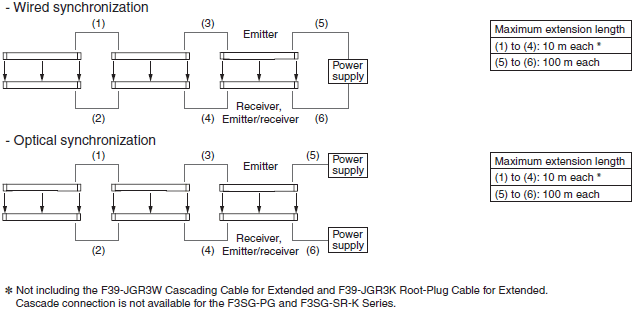
Intelligent Tap F39-SGIT-IL3
| Model | F39-SGIT-IL3 | ||
|---|---|---|---|
| Applicable sensor | F3SG-SR/PG | ||
| Perfor- mance | Response time | Output ON to OFF and OFF to ON: 44 ms max. each * * The response time is the time interval between the changes of the states of the sensor OSSD's and the DO (pin 2). |
|
| Startup waiting time | 3 s max. | ||
| Electrical | Power supply voltage (Vs) | Supplied from external power source: SELV/PELV 24 VDC±20% (ripple p-p 10% max.) USB bus powered: 5 VDC |
|
| Current consumption | 85 mA max. (When connecting 24 VDC power supply and IO-Link Master) | ||
| Safety outputs (OSSD)/ Auxiliary output |
Refer to the ratings and specifications of the F3SG-SR/PG. The safety outputs and auxiliary output of the Intelligent Tap are directly connected to those of the F3SG-SR/PG. |
||
| Digital output for pin 2 (IO-Link) * |
One PNP transistor output Load current: 100 mA max., Residual voltage: 2 V max., Leakage current: 1 mA max. The DO is in the OFF state when the safety outputs are in the ON state. The DO is in the ON state when the safety outputs are in the OFF state. (Regardless of the PNP/NPN setting of the F3SG-SR) |
||
| * For the DO (pin 2) of CN3 | |||
| Input voltage | RESET, EDM | PNP ON voltage: Vs-3 V to Vs (short circuit current: approx. 9.5 mA) *2 OFF voltage: 0 V to 1/2 Vs, or open (short circuit current: approx. 13.0 mA) *2 NPN ON voltage: 0 to 3 V (short circuit current: approx. 13.0 mA) OFF voltage: 1/2 Vs to Vs, or open (short circuit current: approx. 9.5 mA) *2 |
|
| MUTE A/B, PRE-RESET, PSDI *1 |
PNP ON voltage: Vs-3 V to Vs (short circuit current: approx. 4.5 mA) *2 OFF voltage: 0 V to 1/2 Vs, or open (short circuit current: approx. 7.0 mA) *2 NPN ON voltage: 0 to 3 V (short circuit current: approx. 7.0 mA) OFF voltage: 1/2 Vs to Vs, or open (short circuit current: approx. 4.5 mA) *2 |
||
| *1. PSDI is only available for F3SG-SR. *2. The Vs indicates a supply voltage value in your environment. |
|||
| Overvoltage category (IEC 60664-1) |
II | ||
| Protective circuit | Output short-circuit protection, Output reverse polarity protection | ||
| Insulation resistance | 20 MΩ or higher (500 VDC megger) | ||
| Dielectric strength | 1,000 VAC, 50/60 Hz (1 min) | ||
| Functional | Maintenance Information | Error Log Power-ON Time |
|
| Environ- mental | Ambient temperature | Operating | -30 to 55 °C (non-icing) |
| Storage | -30 to 70 °C | ||
| Ambient humidity | Operating | 35% to 85% (non-condensing) | |
| Storage | 35% to 85% | ||
| Degree of protection (IEC 60529) |
IP65, IP67 and IP67G (Covers and cables connected with the Intelligent Tap.) |
||
| Vibration resistance (IEC 61496-1) |
10 to 55 Hz, Multiple amplitude of 0.7 mm, 20 sweeps for all 3 axes | ||
| Shock resistance (IEC 61496-1) |
100 m/s2, 1000 shocks for all 3 axes | ||
| Pollution degree (IEC 60664-1) |
3 | ||
| Connec- tions | To sensors, control box and IO-Link |
M12 connectors: 8-pin (CN1: receiver and CN2: control box) and 5-pin (CN3: IO-Link and CN4: emitter), IP67 and IP67G (JIS C 0920 Annex 1) * rated when mated. * The F3SG-SR meets the degree of protection when the root cable of the F3SG-SR is correctly connected with the F3SG-SR. |
|
| Connection | USB Type-C | ||
| Cable extension | 20 m max. between IO-Link Master and Intelligent Tap, 4 m max.* between PC and Intelligent Tap via USB cable * It is not guaranteed that the Intelligent Tap is connectable to any PC or USB cable. Verify the connection with the USB cable you use. |
||
| IO-Link commu- nications | IO-Link version | Version 1.1 | |
| Baud rate | COM3: 230.4 kbps | ||
| Data length | PD: 4 bytes, OD: 32 bytes (M-sequence type: TYPE_2_V) | ||
| Minimum cycle time | 22 ms | ||
| Material | PBT resin | ||
| Weight | F39-SGIT-IL3: 180 g (when packaged), F39-LITF1: 50 g (when packaged) | ||
| Included accessories | Instruction Sheet and M12 Connector Cover (2 pcs) | ||
Bluetooth® Communication Unit F39-SGBT
| Model | F39-SGBT |
|---|---|
| Applicable sensor | F3SG-SR/PG |
| Power supply voltage (Vs) | 24 VDC±20%, ripple p-p 10% max. (shares power supply of Intelligent Tap) |
| Current consumption | 30 mA max. (shares power supply of Intelligent Tap) |
| Ambient temperature | Operating: -30 to 55 °C (non-icing) Storage: -30 to 70 °C |
| Ambient humidity | Operating: 35% to 85% (non-condensing) Storage: 35% to 85% |
| Degree of protection | IP65, IP67 and IP67G (rated when connected to Intelligent Tap) |
| Vibration resistance | 10 to 55 Hz, Multiple amplitude of 0.7 mm, 20 sweeps for all 3 axes |
| Shock resistance | 100m/s2, 1000 shocks for all 3 axes |
| Type of connection | To be connected to Intelligent Tap |
| Communication system | Bluetooth® Version 3.0 |
| Communication profile | SPP (Serial Port Profile) |
| Transmission distance | Approx. 10 m max. (Output power: Class 2) * |
| Material | PBT resin |
| Weight | 70 g (when packaged) |
* It depends on use environment conditions.
Safety Light Curtain IP69K Model
Main Unit F3SG-SR-K
[][][][] in the model number indicates the protective height in millimeters.
| Model | F3SG-4SRB[][][][]-14-K | F3SG-4SRB[][][][]-25-K | |||
|---|---|---|---|---|---|
| Perfor- mance | Object resolution (Detection capability) |
Opaque objects | |||
| 14-mm dia. | 25-mm dia. | ||||
| Beam gap | 10 mm | 20 mm | |||
| Number of beams | 31 to 179 | 16 to 92 | |||
| Lens size | 4.4 × 3.4 mm (W × H) | 6.7 × 4.5 mm (W × H) | |||
| Protective height | 320 to 1,800 mm | 320 to 1,840 mm | |||
| Operating range | Long | 0.3 to 8.0 m (Typ. 12.0 m) | 0.3 to 16.0 m (Typ. 24.0 m) | ||
| Short | 0.3 to 2.4 m (Typ. 3.6 m) | 0.3 to 5.6 m (Typ. 8.4 m) | |||
| * When operating at an ambient temperature of -10 to -30 °C, use the F3SG-SR with the operating range of 0.3 to 4.0 m in Long Mode and 0.3 to 1.2 m in Short Mode. |
|||||
| Response time | Normal mode | ON to OFF | Optical synchronization: 8 to 18 ms Wired synchronization: 10 to 21 ms |
Optical synchronization: 8 to 13 ms Wired synchronization: 10 to 17 ms |
|
| OFF to ON | Optical synchronization: 40 to 90 ms Wired synchronization: 50 to 105 ms |
Optical synchronization: 40 to 90 ms Wired synchronization: 50 to 85 ms |
|||
| ×2 Slow mode * | ON to OFF | Optical synchronization: 16 to 36 ms Wired synchronization: 20 to 42 ms |
Optical synchronization: 16 to 26 ms Wired synchronization: 20 to 34 ms |
||
| OFF to ON | Optical synchronization: 80 to 180 ms Wired synchronization: 100 to 210 ms |
Optical synchronization: 80 to 130 ms Wired synchronization: 100 to 170 ms |
|||
| ×4 Slow mode * | ON to OFF | Optical synchronization: 32 to 72 ms Wired synchronization: 40 to 84 ms |
Optical synchronization: 32 to 52 ms Wired synchronization: 40 to 68 ms |
||
| OFF to ON | Optical synchronization: 160 to 360 ms Wired synchronization: 200 to 420 ms |
Optical synchronization: 160 to 260 ms Wired synchronization: 200 to 340 ms |
|||
| ×8 Slow mode * | ON to OFF | Optical synchronization: 64 to 144 ms Wired synchronization: 80 to 168 ms |
Optical synchronization: 64 to 104 ms Wired synchronization: 80 to 136 ms |
||
| OFF to ON | Optical synchronization: 320 to 720 ms Wired synchronization: 400 to 840 ms |
Optical synchronization: 320 to 520 ms Wired synchronization: 400 to 680 ms |
|||
| * Selectable by SD Manager 3. | |||||
| Effective aperture angle (EAA) (IEC 61496-2) |
±2.5° max. * Emitter and receiver at operating range of 3 m or greater. | ||||
| Light source | Infrared LEDs, Wavelength: 870 nm | ||||
| Startup waiting time | 3 s max. | ||||
| Elec- trical | Power supply voltage (Vs) | SELV/PELV 24 VDC ±20% (ripple p-p 10% max.) | |||
| Current consumption | Refer to Catalog. | ||||
| Safety outputs (OSSD) | Two PNP or NPN transistor outputs (PNP or NPN is selectable by wiring of power supply.) Load current: 300 mA max., Residual voltage: 2 V max. (except for voltage drop due to cable extension), Capacitive load: 1 μF max., Inductive load: 2.2 H max. *1*2 Leakage current: 1 mA max. (PNP), 2 mA max. (NPN) *3 *1. The residual voltage is 3 V max. when the Intelligent Tap is connected to the sensor. *2. The load inductance is the maximum value when the safety output frequently repeats ON and OFF. When you use the safety output at 4 Hz or less, the usable load inductance becomes larger. *3. These values must be taken into consideration when connecting elements including a capacitive load such as a capacitor. |
||||
| Auxiliary output | Two PNP or NPN transistor 1 outputs (PNP or NPN is selectable by wiring of power supply.) Load current: 100 mA max., Residual voltage: 2 V max. * * The residual voltage is 3 V max. when the Intelligent Tap is connected to the sensor. |
||||
| Output operation mode | Safety output | Light-ON (Safety outputs are turned to the ON state when the receiver receives an emitting signal.) |
|||
| Auxiliary output | Safety output (Inverted signal output: Enable) (default) (Configurable by SD Manager 3) |
||||
| Input voltage | TEST | Light emission stops when connected to 24 VDC ON voltage: Vs-3 V to Vs (short circuit current: approx. 5.0 mA) * OFF voltage: 0 V to 1/2 Vs, or open (short circuit current: approx. 6.0 mA) * Light emission stops when connected to 0 VDC ON voltage: 0 to 3 V (short circuit current: approx. 6.0 mA) OFF voltage: 1/2 Vs to Vs, or open (short circuit current: approx. 5.0 mA) * |
|||
| OPERATING RANGE SELECT INPUT |
Long: 12 V to Vs (short circuit current: approx. 4.2 mA) * or open Short: 0 to 3 V (short circuit current: approx. 4.2 mA) |
||||
| RESET/EDM | PNP ON voltage: Vs-3 V to Vs (short circuit current: approx. 9.5 mA) * OFF voltage: 0 V to 1/2 Vs, or open (short circuit current: approx. 13.0 mA) * NPN ON voltage: 0 to 3 V (short circuit current: approx. 13.0 mA) OFF voltage: 1/2 Vs to Vs, or open (short circuit current: approx. 9.5 mA) * |
||||
| MUTE A/B, RE-RESET, PSDI |
PNP ON voltage: Vs-3V to Vs (short circuit current: approx. 4.5 mA) * OFF voltage: 0 V to 1/2 Vs, or open (short circuit current: approx. 7.0 mA) * NPN ON voltage: 0 to 3 V (short circuit current: approx. 7.0 mA) OFF voltage: 1/2 Vs to Vs, or open (short circuit current: approx. 4.5 mA) * |
||||
| * The Vs indicates a supply voltage value in your environment. | |||||
| Overvoltage category (IEC 60664-1) | II | ||||
| Indicators | Refer to Catalog. | ||||
| Protective circuit | Output short-circuit protection | ||||
| Insulation resistance | 20 M or higher (500 VDC megger) | ||||
| Dielectric strength | 1,000 VAC, 50/60 Hz (1 min) | ||||
| Func- tional | Mutual interference prevention | Optical synchronization: The scan code is fixed to Code A. Wired synchronization: in up to 3 sets |
|||
| Test function | Self-test (at power-on, and during operation) External test (light emission stop function by test input) |
||||
| Safety-related functions | Interlock External Device Monitoring (EDM) Pre-Reset PSDI Fixed Blanking/Floating Blanking Reduced Resolution Muting/Override Mutual Interference Prevention PNP/NPN Selection Response Time Adjustment |
||||
| Environ- mental | Ambient temperature | Operating | -30 to 55 °C (non-icing) | ||
| Storage | -30 to 70 °C | ||||
| Ambient humidity | Operating | 35% to 85% (non-condensing) | |||
| Storage | 35% to 95% | ||||
| Ambient illuminance | Incandescent lamp: 3,000 Ix max. on receiver surface Sunlight: 10,000 Ix max. on receiver surface |
||||
| Degree of protection (IEC 60529) | IEC 60529: IP65 and IP67, ISO 20653: IP69K | ||||
| Vibration resistance (IEC 61496-1) | 10 to 55 Hz, Multiple amplitude of 0.7 mm, 20 sweeps for all 3 axes | ||||
| Shock resistance (IEC 61496-1) | 100 m/s2, 1000 shocks for all 3 axes | ||||
| Pollution degree (IEC 60664-1) | 3 | ||||
| Connec- tions | Root cable | Type of connection | Open-ended type | ||
| Number of wires | Emitter: 5, Receiver: 8 | ||||
| Cable length | 15 m | ||||
| Cable diameter | 6 mm | ||||
| Minimum bending radius |
R5 mm | ||||
| Cable extension |
Refer to Catalog for restrictions on cable extension. | ||||
| Root cable | In optical synchronization: 100 m max. * between power supply and emitter and between power supply and receiver In wired synchronization: 100 m max. * between power supply and emitter, between power supply and receiver, and between emitter and receiver * When the Intelligent Tap (F39-SGIT-IL3) is connected to the sensor, this applies in the case of the rated power supply of 24 VDC to 24 VDC +20%. |
||||
| Material | Pipe: Acrylic resin Cap: SUS316L |
||||
| Weight | Refer to Catalog. | ||||
| Included accessories | Instruction Sheet, Quick Installation Manual, Troubleshooting Guide Sticker |
||||
| Con- formity | Conforming standards | Refer to Catalog. | |||
| Type of ESPE (IEC 61496-1) | Type 4 | ||||
| Performance Level (PL)/ Safety category |
PL e/Category 4 (EN ISO 13849-1:2015) | ||||
| PFHD | 1.1× 10⁻⁸ max. (IEC 61508) | ||||
| Proof test interval TM | Every 20 years (IEC 61508) | ||||
| SFF | 99% (IEC 61508) | ||||
| HFT | 1 (IEC 61508) | ||||
| Classification | Type B (IEC 61508-2) | ||||
Dimensions | Safety Light Curtain - F3SG-SR / PG series
(Unit: mm)
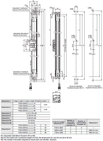
F3SG-SR
Main Unit
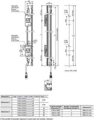
Mounted with Side-Mount Brackets (Intermediate Brackets) (F39-LSGF)
Backside Mounting
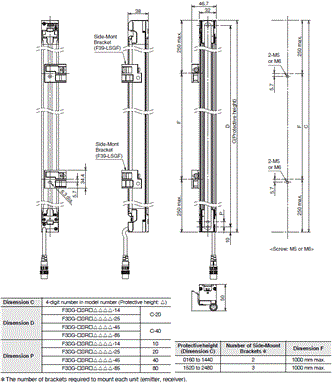
Mounted with Side-Mount Brackets (Intermediate Brackets) (F39-LSGF)
Side Mounting
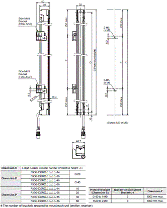
Mounted with Adjustable Side-Mount Brackets (Intermediate Brackets) (F39-LSGA)
Backside Mounting
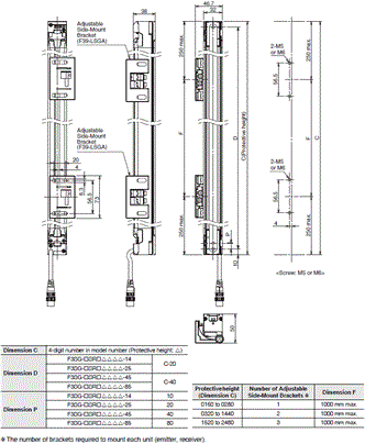
Mounted with Adjustable Side-Mount Brackets (Intermediate Brackets) (F39-LSGA)
Side Mounting
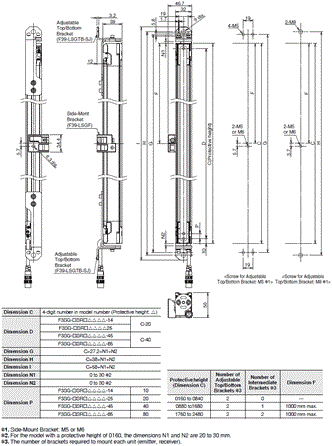
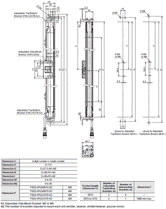
Mounted with Adjustable Top/Bottom Brackets (F3SJ, F3SN Adapter) (F39-LSGTB-SJ) and Side-Mount Brackets (Intermediate Brackets) (F39-LSGF)
Backside Mounting
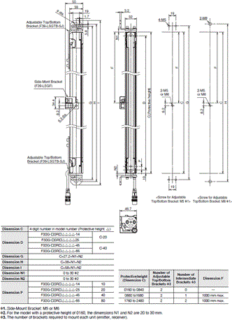
Mounted with Adjustable Top/Bottom Brackets (F3SJ, F3SN Adapter) (F39-LSGTB-SJ) and Side-Mount Brackets (Intermediate Brackets) (F39-LSGF)
Side Mounting
Mounted with Adjustable Top/Bottom Brackets (F3SJ, F3SN Adapter) (F39-LSGTB-SJ) and Adjustable Side-Mount Brackets (Intermediate Brackets) (F39-LSGA)
Backside Mounting
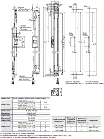
Mounted with Adjustable Top/Bottom Brackets (F3SJ, F3SN Adapter) (F39-LSGTB-SJ) and Adjustable Side-Mount Brackets (Intermediate Brackets) (F39-LSGA)
Side Mounting
F3SG-PG
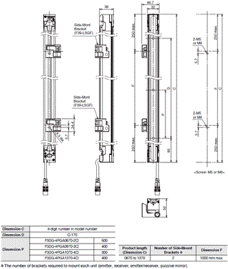
Main Unit
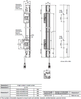
Mounted with Side-Mount Brackets (Intermediate Brackets) (F39-LSGF)
Backside Mounting
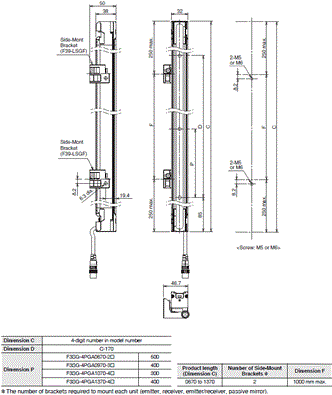
Mounted with Side-Mount Brackets (Intermediate Brackets) (F39-LSGF)
Side Mounting
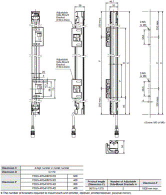
Mounted with Adjustable Side-Mount Brackets (Intermediate Brackets) (F39-LSGA)
Backside Mounting
Mounted with Adjustable Side-Mount Brackets (Intermediate Brackets) (F39-LSGA)
Side Mounting
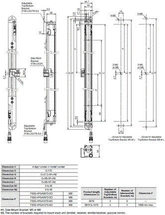
Mounted with Adjustable Top/Bottom Brackets (F3SJ, F3SN Adapter) (F39-LSGTB-SJ) and Side-Mount Brackets (Intermediate Brackets) (F39-LSGF)
Backside Mounting
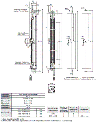
Mounted with Adjustable Top/Bottom Brackets (F3SJ, F3SN Adapter) (F39-LSGTB-SJ) and Side-Mount Brackets (Intermediate Brackets) (F39-LSGF)
Side Mounting
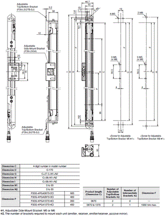
Mounted with Adjustable Top/Bottom Brackets (F3SJ, F3SN Adapter) (F39-LSGTB-SJ) and Adjustable Side-Mount Brackets (Intermediate Brackets) (F39-LSGA)
Backside Mounting
Mounted with Adjustable Top/Bottom Brackets (F3SJ, F3SN Adapter) (F39-LSGTB-SJ) and Adjustable Side-Mount Brackets (Intermediate Brackets) (F39-LSGA)
Side Mounting
F3SG-SR/PG Accessories
Bracket
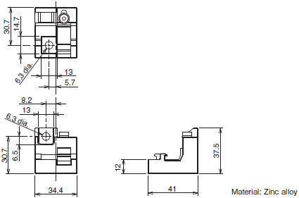
Side-Mount Bracket (Intermediate Bracket) (F39-LSGF, sold separately)
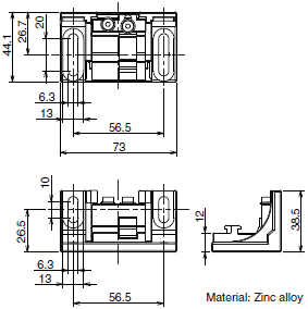
Adjustable Side-Mount Bracket (Intermediate Bracket) (F39-LSGA, sold separately)
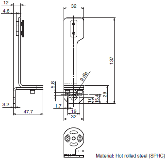
Adjustable Top/Bottom Bracket (F3SJ, F3SN Adapter) (F39-LSGTB-SJ, sold separately)
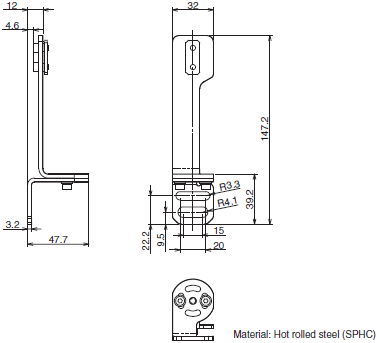
Adjustable Top/Bottom Bracket (F3SG-RA/RE Adapter) (F39-LSGTB-RE, sold separately)
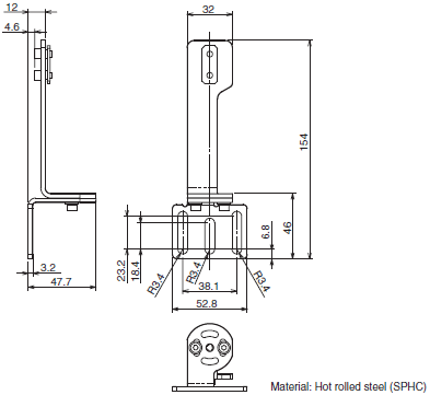
Adjustable Top/Bottom Bracket (MS4800, F3SR Adapter) (F39-LSGTB-MS, sold separately)
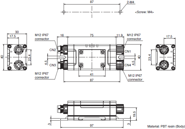
Intelligent Tap
Intelligent Tap (F39-SGIT-IL3, sold separately)
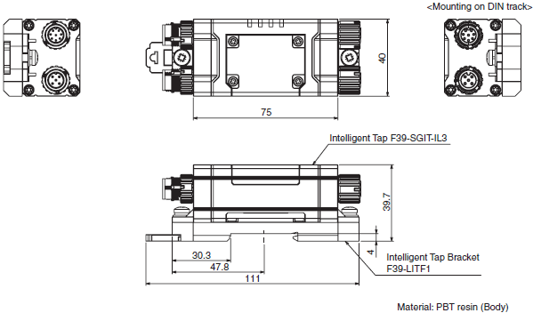
Intelligent Tap Bracket (F39- LITF1, sold separately)
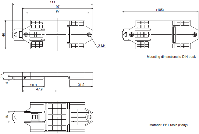
Assembly Dimensions (Intelligent Tap/ Intelligent Tap Bracket)
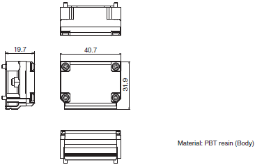
Bluetooth® Communication Unit (F39-SGBT, sold separately)
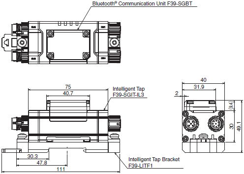
Assembly Dimensions (Intelligent Tap/Bluetooth® Communication Unit/Intelligent Tap Bracket)
Spatter Protection Cover
Spatter Protection Cover (F39-HSG[][][][], sold separately)

Connecting Cables
Root-Straight Cable
Root-Straight Cable for Emitter (F39-JG[]C-L, sold separately)

Root-Straight Cable for receiver or emitter/receiver of F3SG-PG Perimeter Guarding Passive Mirror (F39-JG[]C-D, sold separately)

Root-Plug Cable for Extended
Root-Plug Cable for Extended for Emitter (F39-JGR[]K-L, sold separately)

Root-Plug Cable for Extended for receiver or emitter/receiver of F3SG-PG Perimeter Guarding Passive Mirror (F39-JGR[]K-D, sold separately)

Extended Socket-Straight Cable
Extended Socket-Straight Cable for Emitter (F39-JG[]A-L, sold separately)

Extended Socket-Straight Cable for receiver or emitter/receiver of F3SG-PG Perimeter Guarding Passive Mirror (F39-JG[]A-D, sold separately)

Extended Plug-Socket Cable
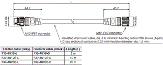
Extended Plug-Socket Cable for Emitter: Cable for extension (F39-JG[]B-L, sold separately)

Extended Plug-Socket Cable for receiver or emitter/receiver of F3SG-PG Perimeter Guarding Passive Mirror: Cable for extension (F39-JG[]B-D, sold separately)
Cascading Cable for Extended (F39-JGR3W, sold separately) (two cables per set, one for emitter and one for receiver)
Emitter Cascading Cable for Extended

Receiver Cascading Cable for Extended

Side-by-side Cascading Cable (F39-JGR12L, sold separately) (two cables per set, one for emitter and one for receiver)
Side-by-side Cascading Cable for Emitter

Side-by-side Cascading Cable for Receiver

Conversion Cable
F3SJ-B/A Conversion Cable for Emitter (F39-JGR3K-SJ-L, sold separately)

F3SJ-B/A Conversion Cable for Receiver (F39-JGR3K-SJ-D, sold separately)

F3SG-RE Conversion Cable for Emitter (F39-JGR3K-RE-L, sold separately)

F3SG-RE Conversion Cable for Receiver (F39-JGR3K-RE-D, sold separately)

MS48 Conversion Cable for Emitter (F39-JGR3K-MS-L, sold separately)

MS48 Conversion Cable for Receiver (F39-JGR3K-MS-D, sold separately)

Y-Joint Plug/Socket Connector (F39-GCNY2, sold separately)
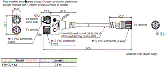
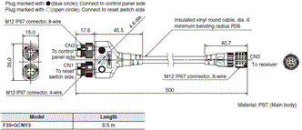
Reset Switch Connector (F39-GCNY3, sold separately)
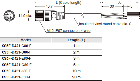
Connector Connected to Cable, Socket on One Cable End (XS5F-D421-[]80-F, sold separately)
Lamp
Lamp (F39-SGLP, sold separately)
Muting Sensor Arm Mounter
Muting Sensor Arm Mounter (F39-FMA[][][][], sold separately)
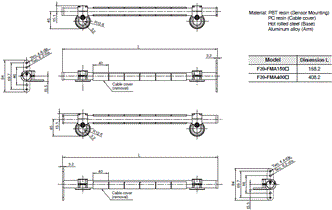
Muting Sensor Arm Mounter Bracket for SLC (F39-LMAF1, sold separately)
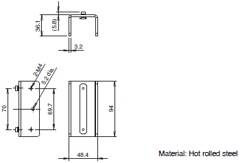
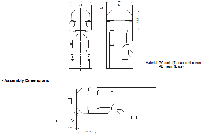
• Assembly Dimensions
Mounting F39-FMA[][][][]-T on the Muting Sensor Arm Mounter Bracket for SLC (F39-LMAF1)

Mounting F39-FMA[][][][]-R on the Floor Mount Column (F39-ST[][][][])

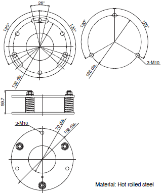
Mount-Column Adjustable Base
F39-STB
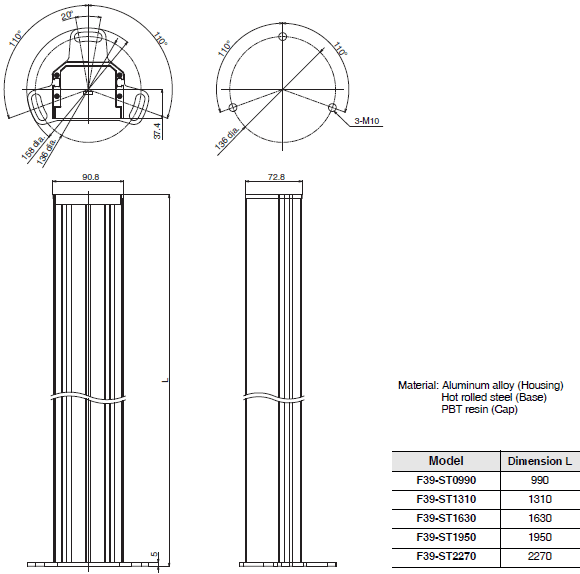
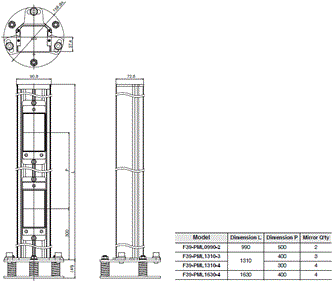
Floor Mount Column
F39-ST[][][][]
• Assembly Dimensions (Mount-Column Adjustable Base /Floor Mount Column)
F39-STB/F39-ST[][][][]
Mirror Column
F39-SML[][][][]
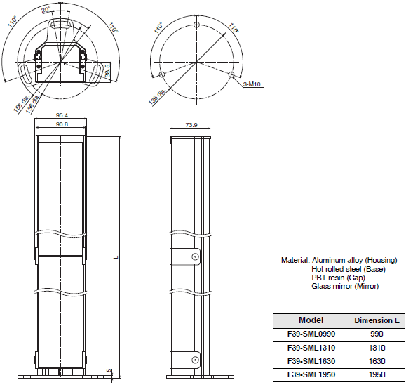
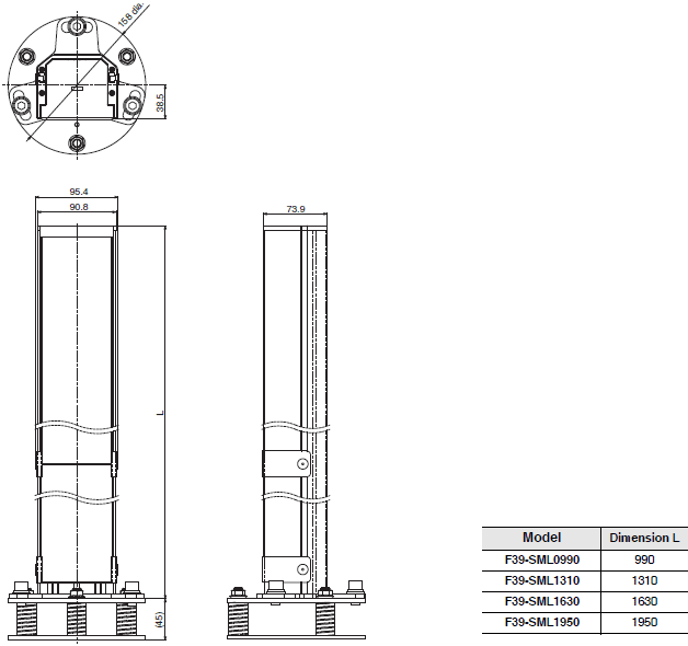
• Assembly Dimensions (Mount-Column Adjustable Base /Mirror Column)
F39-STB/F39-SML[][][][]
F39-PML[][][][]
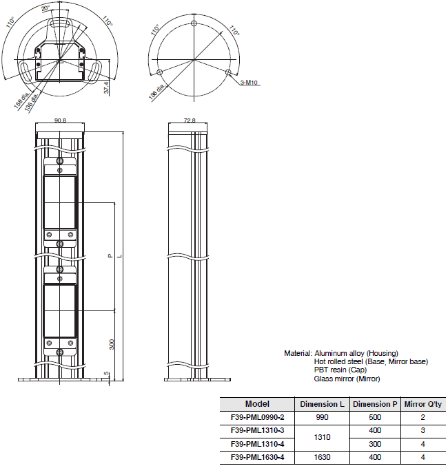
• Assembly Dimensions (Mount-Column Adjustable Base /Mirror Column)
F39-STB/F39-PML[][][][]
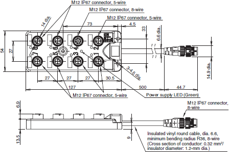
Muting Sensor Connection Box
F39-GCN5
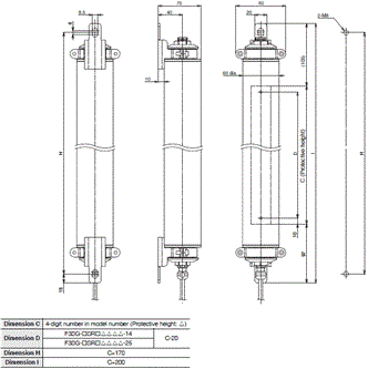
F3SG-SR-K
Main Unit
Mounted with IP69K Model Mounting Brackets (F39-LSGTB-K)
Side mounting and backside mounting
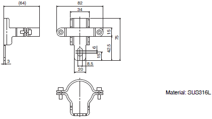
Accessories
Bracket
IP69K Model Mounting Bracket (F39-LSGTB-K, sold separately)
Features | Safety Light Curtain - F3SG-SR / PG series
Conforms to major international standards
- Area Beam Indicators (ABI) - Tri-color indicators for easy & instant status
- Harsh Environments – Cold storage, metal working (oil mist), food processing
- Back-up & restore settings with Intelligent Tap – can reduce maintenance setup time by 90%
- Perfect fit – Protective heights in 40 mm increments
- IO-Link – Easy remote monitoring of process & service data
- A broad line-up, from finger protection to body protection
Properties | Safety Light Curtain - F3SG-SR / PG series
| Safety Light Curtain | F3SG-SR | F3SG-PG |
|---|---|---|
| Object Resolution | Ø 14 / 25 / 45 / 85 mm | 30 mm |
| Beam gap | 10 / 20 / 40 / 80 mm | 300 - 500 mm |
| Number of beams | 15-199 / 8-124 / 6-38 / 4-12 | 2-4 |
| Dimensions | 160-2000 / 160-2480 / 240-1520 / 280-920 mm | 670 / 970 / 1070 / 1370 mm |
| Height (W x H) mm | 4.4 x 3.4 / 6.7 x 4.5 | 8.1 x 12.8 |
| Enclosure Rating IP | 65 / 67 / 67G | 65 / 67 |
| Rangevoltage | 24 VDC | |
| Safety Output | 2 Port(PNPorNPN) , 24 VDC Current300 mA | |
| เอาต์พุตเสริม | 1 Port(PNPorNPN), 24 VDCCurrent 100 mA | |
Safety Light Curtain - F3SG-SR / PG series
ดาวน์โหลดไฟล์ PDF
คุณสมบัติ | Safety Light Curtain - F3SG-SR / PG series
ม่านแสงนิรภัย พร้อมประสิทธิภาพในการวางแนวที่ดีขึ้น การวิเคราะห์ขั้นสูง และช่วยลดต้นทุนในการติดตั้ง
- สอดคล้องตามมาตรฐานสากล
- Area Beam Indicators: มีไฟแสดงสถานะ 3 สี สำหรับตรวจสอบสถานะที่ง่าย และรวดเร็ว
- ทนต่อสภาพแวดล้อม เช่น ห้องเย็น งานโลหะ(ละอองน้ำมัน) แปรรูปอาหาร
- สามารถสำรอง และกู้คืนการตั้งค่าได้ ทำให้ลดเวลาการบำรุงรักษา 90%
- ความสูงของม่านแสงนิรภัย เพิ่มได้ตั้งแต่ 40-1000 มิลลิเมตร
- ง่ายต่อตรวจสอบข้อมูลระยะไกล
- สามารถตรวจจับ และป้องกันได้ตั้งแต่นิ้วมือ จนถึง ร่างกาย
ข้อมูลจำเพาะ | Safety Light Curtain - F3SG-SR / PG series
| Safety Light Curtain | F3SG-SR | F3SG-PG |
|---|---|---|
| ความสามารถในการตรวจจับวัตถุ | Ø 14 / 25 / 45 / 85 mm | 30 mm |
| ระยะห่างของลำแสง | 10 / 20 / 40 / 80 mm | 300 - 500 mm |
| จำนวนของลำแสง | 15-199 / 8-124 / 6-38 / 4-12 | 2-4 |
| ความสูง | 160-2000 / 160-2480 / 240-1520 / 280-920 mm | 670 / 970 / 1070 / 1370 mm |
| ขนาด (W x H) mm | 4.4 x 3.4 / 6.7 x 4.5 | 8.1 x 12.8 |
| IP | 65 / 67 / 67G | 65 / 67 |
| แรงดัน | 24 VDC | |
| Safety Output | 2 ช่องเลือกได้ระหว่าง PNP กับ NPN, แรงดัน 24 VDC กระแส 300 mA | |
| เอาต์พุตเสริม | 1 ช่องเลือกได้ระหว่าง PNP กับ NPN, แรงดัน 24 VDC กระแส 100 mA | |


 Your Lift