
OMRON Safety Light Curtain - F3SG-R series
Safety Light Curtain - F3SG-R series

Model Numbers | Safety Light Curtain - F3SG-R series
F3SG-RA Advanced type
Main Units
Safety Light Curtain
Finger protection
| Number of beams | Protective height (mm) | Model |
|---|---|---|
| 15 | 160 | F3SG-4RA0160-14 |
| 23 | 240 | F3SG-4RA0240-14 |
| 31 | 320 | F3SG-4RA0320-14 |
| 39 | 400 | F3SG-4RA0400-14 |
| 47 | 480 | F3SG-4RA0480-14 |
| 55 | 560 | F3SG-4RA0560-14 |
| 63 | 640 | F3SG-4RA0640-14 |
| 71 | 720 | F3SG-4RA0720-14 |
| 79 | 800 | F3SG-4RA0800-14 |
| 87 | 880 | F3SG-4RA0880-14 |
| 95 | 960 | F3SG-4RA0960-14 |
| 103 | 1040 | F3SG-4RA1040-14 |
| 111 | 1120 | F3SG-4RA1120-14 |
| 119 | 1200 | F3SG-4RA1200-14 |
| 127 | 1280 | F3SG-4RA1280-14 |
| 135 | 1360 | F3SG-4RA1360-14 |
| 143 | 1440 | F3SG-4RA1440-14 |
| 151 | 1520 | F3SG-4RA1520-14 |
| 159 | 1600 | F3SG-4RA1600-14 |
| 167 | 1680 | F3SG-4RA1680-14 |
| 175 | 1760 | F3SG-4RA1760-14 |
| 183 | 1840 | F3SG-4RA1840-14 |
| 191 | 1920 | F3SG-4RA1920-14 |
| 199 | 2000 | F3SG-4RA2000-14 |
| 207 | 2080 | F3SG-4RA2080-14 |
Hand and arm protection
| Number of beams | Protective height (mm) | Model |
|---|---|---|
| 8 | 190 | F3SG-4RA0190-30 |
| 12 | 270 | F3SG-4RA0270-30 |
| 16 | 350 | F3SG-4RA0350-30 |
| 20 | 430 | F3SG-4RA0430-30 |
| 24 | 510 | F3SG-4RA0510-30 |
| 28 | 590 | F3SG-4RA0590-30 |
| 32 | 670 | F3SG-4RA0670-30 |
| 36 | 750 | F3SG-4RA0750-30 |
| 40 | 830 | F3SG-4RA0830-30 |
| 44 | 910 | F3SG-4RA0910-30 |
| 48 | 990 | F3SG-4RA0990-30 |
| 52 | 1070 | F3SG-4RA1070-30 |
| 56 | 1150 | F3SG-4RA1150-30 |
| 60 | 1230 | F3SG-4RA1230-30 |
| 64 | 1310 | F3SG-4RA1310-30 |
| 68 | 1390 | F3SG-4RA1390-30 |
| 72 | 1470 | F3SG-4RA1470-30 |
| 76 | 1550 | F3SG-4RA1550-30 |
| 80 | 1630 | F3SG-4RA1630-30 |
| 84 | 1710 | F3SG-4RA1710-30 |
| 88 | 1790 | F3SG-4RA1790-30 |
| 92 | 1870 | F3SG-4RA1870-30 |
| 96 | 1950 | F3SG-4RA1950-30 |
| 100 | 2030 | F3SG-4RA2030-30 |
| 104 | 2110 | F3SG-4RA2110-30 |
| 108 | 2190 | F3SG-4RA2190-30 |
| 112 | 2270 | F3SG-4RA2270-30 |
| 116 | 2350 | F3SG-4RA2350-30 |
| 120 | 2430 | F3SG-4RA2430-30 |
| 124 | 2510 | F3SG-4RA2510-30 |
Accessories (Sold separately)
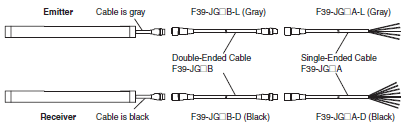
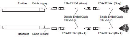
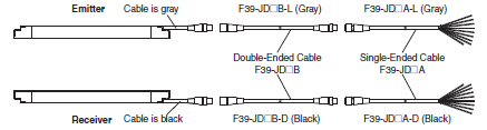
Safety light curtain connecting cable
Single-Ended Cable *
| Appearance | Type | Cable length | Specifications | Model |
|---|---|---|---|---|
 |
For emitter M12 connector (5-pin), 5 wires Color: Gray |
3 m |  |
F39-JG3A-L |
| 7 m | F39-JG7A-L | |||
| 10 m | F39-JG10A-L | |||
| 15 m | F39-JG15A-L | |||
| 20 m | F39-JG20A-L | |||
| For receiver M12 connector (8-pin), 8 wires Color: Black |
3 m |  |
F39-JG3A-D | |
| 7 m | F39-JG7A-D | |||
| 10 m | F39-JG10A-D | |||
| 15 m | F39-JG15A-D | |||
| 20 m | F39-JG20A-D |
* A set of two Single-Ended Cables (one for emitter and one for receiver) is also available.
Model: Model number without the -L/-D at the end (F39-JG[]A)
Note: To extend the cable length to more than 20 m, add the F39-JG[]B Double-Ended Cable.
Double-Ended Cable *
For cable extension and simple wiring
| Appearance | Type | Cable length | Specifications | Model |
|---|---|---|---|---|
 |
For emitter M12 connector (5-pin) on both ends Color: Gray |
0.5 m |  |
F39-JGR5B-L |
| 1 m | F39-JG1B-L | |||
| 3 m | F39-JG3B-L | |||
| 5 m | F39-JG5B-L | |||
| 7 m | F39-JG7B-L | |||
| 10 m | F39-JG10B-L | |||
| 15 m | F39-JG15B-L | |||
| 20 m | F39-JG20B-L | |||
| For receiver M12 connector (8-pin) on both ends Color: Black |
0.5 m |  |
F39-JGR5B-D | |
| 1 m | F39-JG1B-D | |||
| 3 m | F39-JG3B-D | |||
| 5 m | F39-JG5B-D | |||
| 7 m | F39-JG7B-D | |||
| 10 m | F39-JG10B-D | |||
| 15 m | F39-JG15B-D | |||
| 20 m | F39-JG20B-D |
* A set of two Double-Ended Cables (one for emitter and one for receiver) is also available.
Model: Model number without the -L/-D at the end (F39-JG[]B)
Note: To extend the cable length to more than 20 m, add the F39-JG[]B Double-Ended Cable to the F39-JG[]A Single-
Ended Cable.
To extend the cable length to more than 40 m, add several Double-Ended Cables to the Single-Ended Cable.
Example: To extend the cable length to 50 m, connect two F39-JG20B (20 m) cables and one F39-JG10A (10 m)
cable.
Connection example
Y-Joint Plug/Socket Connector for F3SG-4RA[][][][]-14/-4RA[][][][]-30
For reduced wiring
| Appearance | Type | Cable length | Specifications | Model |
|---|---|---|---|---|
 |
M12 connectors. Used for reduced wiring. |
0.5 m |  |
F39-GCNY2 |
* Order the cable for emitter (end of model: -L) and the cable for receiver (end of model: -D).
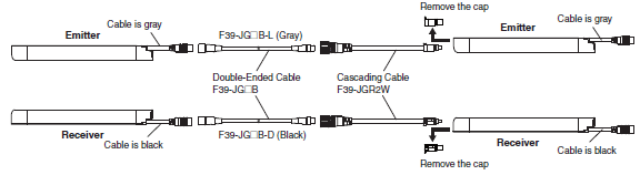
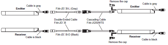
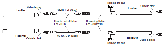
Cascading Cable (2 cables per set, for emitter and receiver)
| Appearance | Specifications | Cable length | Specifications | Model |
|---|---|---|---|---|
 |
Emitter cable: Cap (5-pin), M12 connector (5-pin) Receiver cable: Cap (8-pin), M12 connector (8-pin) |
0.2 m |  |
F39-JGR2W |
Note: The Double-Ended Cable (up to 10 m: F39-JG10B) can be added to extend the cable length between the series-connected sensors.
Cable length between sensors: 10 m max. (not including cascading cable (F39-JGR2W) and power cable)
Connection example
Sensor Mounting Brackets
| Appearance | Specification | Application | Model |
|---|---|---|---|
 |
Standard Fixed Bracket |
Bracket to mount the F3SG-R. Side mounting and backside mounting possible. (This is included as a standard accessory with the product. It comes as a set of two Brackets. Refer to note *1 for the number of sets provided with each model.) |
F39-LGF |
 |
Standard Adjustable Bracket |
Bracket to mount the F3SG-R. Beam alignment after mounting possible. The angle adjustment range is ±15°. Side mounting and backside mounting possible. (Sold separately as a set of two Brackets. Refer to note *1 for the number of sets required for each model.) |
F39-LGA |
 |
Top/Bottom Adjustable Bracket *2 |
Bracket to mount the F3SG-R. Use this bracket at the top and bottom positions of the F3SG-R. Beam alignment after mounting possible. The angle adjustment range is ±22.5°. Side mounting and backside mounting possible. (Sold separately. 4 brackets per set.) |
F39-LGTB |
 |
Top/Bottom Adjustable Bracket *2 (For user-made mounting part) |
Top/Bottom Adjustable Bracket without a bracket to mount to the wall. Use the user's own wall mounting part to suit the machine. (Sold separately. 4 brackets per set.) |
F39-LGTB-1 |
*1. [for F3SG-4RA[][][][]-14]
- Protective height of 0160 to 1200: 2 sets, Protective height of 1280 to 2080: 3 sets
[for F3SG-4RA[][][][]-30]
- Protective height of 0190 to 1230: 2 sets, Protective height of 1310 to 2270: 3 sets, Protective height of 2350 to
2510: 4 sets
*2. Top/Bottom Adjustable Bracket cannot be used with the Standard Fixed Bracket. Use with the Standard Adjustable Bracket.
Using Top/Bottom Adjustable Brackets with Standard Adjustable Brackets
F3SG-4RA[][][][]-14:
Protective height of 1040 or less:
The Standard Adjustable Bracket is not required.
Please purchase 1 set of Top/Bottom Adjustable Brackets (F39-LGTB(-1)).
Protective height of 1120 to 1920:
Please purchase 1 set of Top/Bottom Adjustable Brackets (F39-LGTB(-1)) and 1 set of Standard Adjustable
Brackets (F39-LGA).
Protective height of 2000 to 2080:
Please purchase 1 set of Top/Bottom Adjustable Brackets (F39-LGTB(-1)) and 2 sets of Standard Adjustable
Brackets (F39-LGA).
F3SG-4RA[][][][]-30:
Protective height of 1070 or less:
The Standard Adjustable Bracket is not required.
Please purchase 1 set of Top/Bottom Adjustable Brackets (F39-LGTB(-1)).
Protective height of 1150 to 1950:
Please purchase 1 set of Top/Bottom Adjustable Brackets (F39-LGTB(-1)) and 1 set of Standard Adjustable
Brackets (F39-LGA).
Protective height of 2030 to 2510:
Please purchase 1 set of Top/Bottom Adjustable Brackets (F39-LGTB(-1)) and 2 sets of Standard Adjustable
Brackets (F39-LGA).
Interface units and configuration tool SD Manager 2
| Appearance | Type | Specifications | Model |
|---|---|---|---|
 |
SD Manager 2 | The Configuration Tool SD Manager 2 is available to download from our website at http://www.ia.omron.com/f3sg-r_tool. To change the settings of the F3SG-RA using SD Manager 2, it is necessary to set the receiver's two DIP switches No. 8 to ON. |
- |
 |
Interface Unit | F39-GIF interface unit to connect the F3SG-RA receiver to a USB port of the PC Accessories: 0.3-m Dedicated Cable 1 (1), 2-m Dedicated Cable 2 (1), Instruction Manual |
F39-GIF |
 |
Bluetooth Communication Unit |
F39-BT bluetooth unit to enable bluetooth on the F3SG-RA IP67 rated when mated. |
F39-BT |
Lamp
| Appearance | Type | Specifications | Model |
|---|---|---|---|
 |
Lamp unit | The lamp unit can be connected to a receiver and turned ON based on the operation of F3SG-RA/RR. The lamp can indicate red, orange, and green colors, to which three different states can be assigned. IP67 rated when mated. |
F39-LP |
| Lamp and Bluetooth Communication Unit |
F39-BTLP |
End Cap
| Appearance | Specifications | Model |
|---|---|---|
 |
Housing color: Black For both emitter and receiver (Attached to the F3SG-RA. The End Cap can be purchased if lost.) IP67 rated when mated. |
F39-CNM |
Laser Pointer for F3SG-R
| Appearance | Specifications | Model |
|---|---|---|
 |
The laser pointer is attached on the optical surface of the F3SG-R to help coarse adjustment of beams. |
F39-PTG |
Spatter Protection Cover (2 covers per set, one for emitter and one for receiver)
Spatter Protection Covers include mounting brackets.
For Safety Light Curtain models of the protective height of 2,000 mm or longer, use two Spatter Protection Covers of different lengths.
| Appearance | Safety Light Curtain Model | Model | |
|---|---|---|---|
| Finger protection | Hand and arm protection | ||
 |
F3SG-4RA0160-14 | F3SG-4RA0190-30 | F39-HGA0200 |
| F3SG-4RA0240-14 | F3SG-4RA0270-30 | F39-HGA0280 | |
| F3SG-4RA0320-14 | F3SG-4RA0350-30 | F39-HGA0360 | |
| F3SG-4RA0400-14 | F3SG-4RA0430-30 | F39-HGA0440 | |
| F3SG-4RA0480-14 | F3SG-4RA0510-30 | F39-HGA0520 | |
| F3SG-4RA0560-14 | F3SG-4RA0590-30 | F39-HGA0600 | |
| F3SG-4RA0640-14 | F3SG-4RA0670-30 | F39-HGA0680 | |
| F3SG-4RA0720-14 | F3SG-4RA0750-30 | F39-HGA0760 | |
| F3SG-4RA0800-14 | F3SG-4RA0830-30 | F39-HGA0840 | |
| F3SG-4RA0880-14 | F3SG-4RA0910-30 | F39-HGA0920 | |
| F3SG-4RA0960-14 | F3SG-4RA0990-30 | F39-HGA1000 | |
| F3SG-4RA1040-14 | F3SG-4RA1070-30 | F39-HGA1080 | |
| F3SG-4RA1120-14 | F3SG-4RA1150-30 | F39-HGA1160 | |
| F3SG-4RA1200-14 | F3SG-4RA1230-30 | F39-HGA1240 | |
| F3SG-4RA1280-14 | F3SG-4RA1310-30 | F39-HGA1320 | |
| F3SG-4RA1360-14 | F3SG-4RA1390-30 | F39-HGA1400 | |
| F3SG-4RA1440-14 | F3SG-4RA1470-30 | F39-HGA1480 | |
| F3SG-4RA1520-14 | F3SG-4RA1550-30 | F39-HGA1560 | |
| F3SG-4RA1600-14 | F3SG-4RA1630-30 | F39-HGA1640 | |
| F3SG-4RA1680-14 | F3SG-4RA1710-30 | F39-HGA1720 | |
| F3SG-4RA1760-14 | F3SG-4RA1790-30 | F39-HGA1800 | |
| F3SG-4RA1840-14 | F3SG-4RA1870-30 | F39-HGA1880 | |
| F3SG-4RA1920-14 | F3SG-4RA1950-30 | F39-HGA1960 | |
| F3SG-4RA2000-14 | F3SG-4RA2030-30 | F39-HGA1480 | |
| F39-HGA0550 | |||
| F3SG-4RA2080-14 | F3SG-4RA2110-30 | F39-HGA1560 | |
| F39-HGA0550 | |||
| - | F3SG-4RA2190-30 | F39-HGA1640 | |
| F39-HGA0550 | |||
| - | F3SG-4RA2270-30 | F39-HGA1720 | |
| F39-HGA0550 | |||
| - | F3SG-4RA2350-30 | F39-HGA1800 | |
| F39-HGA0550 | |||
| - | F3SG-4RA2430-30 | F39-HGA1880 | |
| F39-HGA0550 | |||
| - | F3SG-4RA2510-30 | F39-HGA1960 | |
| F39-HGA0550 | |||
Note:
1. The operating range of the Safety Light Curtain attached with the product is 10% shorter than the rating.
2. The product extends over the DIP Switch cover of the Safety Light Curtain. Be sure to use the product only after all required settings are made to the DIP Switch.
Test Rod
| Diameter | Model |
|---|---|
| 14 mm dia. | F39-TRD14 |
| 30 mm dia. | F39-TRD30 |
F3SG-RR Robust type
Main Units
Safety Light Curtain
Finger protection
| Number of beams | Protective height (mm) | Model |
|---|---|---|
| 23 | 240 | F3SG-4RR0240-14 |
| 31 | 320 | F3SG-4RR0320-14 |
| 39 | 400 | F3SG-4RR0400-14 |
| 47 | 480 | F3SG-4RR0480-14 |
| 55 | 560 | F3SG-4RR0560-14 |
| 63 | 640 | F3SG-4RR0640-14 |
| 71 | 720 | F3SG-4RR0720-14 |
| 79 | 800 | F3SG-4RR0800-14 |
| 87 | 880 | F3SG-4RR0880-14 |
| 95 | 960 | F3SG-4RR0960-14 |
| 103 | 1040 | F3SG-4RR1040-14 |
| 111 | 1120 | F3SG-4RR1120-14 |
| 119 | 1200 | F3SG-4RR1200-14 |
| 127 | 1280 | F3SG-4RR1280-14 |
| 135 | 1360 | F3SG-4RR1360-14 |
| 143 | 1440 | F3SG-4RR1440-14 |
| 151 | 1520 | F3SG-4RR1520-14 |
| 159 | 1600 | F3SG-4RR1600-14 |
| 167 | 1680 | F3SG-4RR1680-14 |
| 175 | 1760 | F3SG-4RR1760-14 |
| 183 | 1840 | F3SG-4RR1840-14 |
| 191 | 1920 | F3SG-4RR1920-14 |
Hand and arm protection
| Number of beams | Protective height (mm) | Model |
|---|---|---|
| 12 | 240 | F3SG-4RR0240-25 |
| 16 | 320 | F3SG-4RR0320-25 |
| 20 | 400 | F3SG-4RR0400-25 |
| 24 | 480 | F3SG-4RR0480-25 |
| 28 | 560 | F3SG-4RR0560-25 |
| 32 | 640 | F3SG-4RR0640-25 |
| 36 | 720 | F3SG-4RR0720-25 |
| 40 | 800 | F3SG-4RR0800-25 |
| 44 | 880 | F3SG-4RR0880-25 |
| 48 | 960 | F3SG-4RR0960-25 |
| 52 | 1040 | F3SG-4RR1040-25 |
| 56 | 1120 | F3SG-4RR1120-25 |
| 60 | 1200 | F3SG-4RR1200-25 |
| 64 | 1280 | F3SG-4RR1280-25 |
| 68 | 1360 | F3SG-4RR1360-25 |
| 72 | 1440 | F3SG-4RR1440-25 |
| 76 | 1520 | F3SG-4RR1520-25 |
| 80 | 1600 | F3SG-4RR1600-25 |
| 84 | 1680 | F3SG-4RR1680-25 |
| 88 | 1760 | F3SG-4RR1760-25 |
| 92 | 1840 | F3SG-4RR1840-25 |
| 96 | 1920 | F3SG-4RR1920-25 |
Accessories (Sold separately)
Safety light curtain connecting cable
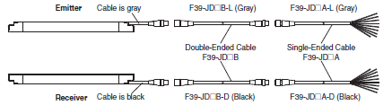
Single-Ended Cable (Oil-Resistant Cable)
| Appearance | Type | Cable length | Specifications | Model |
|---|---|---|---|---|
 |
For emitter M12 connector (8-pin), 5 wires Color: Gray |
3 m |  IP67 and IP67G (JIS C 0920 Annex 1) * rated when mated. * F3SG-RR meets the degree of protection when this cable is correctly connected with the power cable of the F3SG-RR. The degree of protection is not satisfied with the part where cable wires are uncovered. |
F39-JD3RA-L |
| 7 m | F39-JD7RA-L | |||
| For receiver M12 connector (8-pin), 8 wires Color: Black |
3 m | F39-JD3RA-D | ||
| 7 m | F39-JD7RA-D |
Note: To extend the cable length to more than 7 m, add the F39-JD[]B Double-Ended Cable.
When the Double-Ended Cable is used, protect it from cutting oil.
Single-Ended Cable (2 cables per set, one for emitter and one for receiver) *
| Appearance | Cable length | Specifications | Model |
|---|---|---|---|
 |
3 m |  IP67* rated when mated. IP67* rated when mated. * When the accessory is used, protect it from cutting oil. |
F39-JD3A |
| 7 m | F39-JD7A | ||
| 10 m | F39-JD10A | ||
| 15 m | F39-JD15A | ||
| 20 m | F39-JD20A |
* The cable for emitter and the cable for receiver are available separately. Add '-L' for emitter or '-D' for receiver to the end of the model number when you order.
Single-Ended Cable for Emitter: F39-JD[]A-L, Single-Ended Cable for Receiver: F39-JD[]A-D
Note:
1. Use the F39-JD[]RA-L/-D for applications where cutting oil resistance is required.
2. To extend the cable length to more than 20 m, add the F39-JD[]B Double-Ended Cable.
Double-Ended Cable (2 cables per set, one for emitter and one for receiver) *
| Appearance | Cable length | Specifications | Model |
|---|---|---|---|
 |
0.5 m |  IP67* rated when mated. IP67* rated when mated. * When the accessory is used, protect it from cutting oil. |
F39-JDR5B |
| 1 m | F39-JD1B | ||
| 3 m | F39-JD3B | ||
| 5 m | F39-JD5B | ||
| 7 m | F39-JD7B | ||
| 10 m | F39-JD10B | ||
| 15 m | F39-JD15B | ||
| 20 m | F39-JD20B |
* The cable for emitter and the cable for receiver are available separately. Add '-L' for emitter or '-D' for receiver to the end of the model number when you order.
Double-Ended Cable for Emitter: F39-JD[]B-L, Double-Ended Cable for Receiver: F39-JD[]B-D
Note: To extend the cable length to more than 20 m, add the F39-JD[]B Double-Ended Cable to the F39-JD[]A Single- Ended Cable.
To extend the cable length to more than 40 m, add several Double-Ended Cables to the Single-Ended Cable.
Example: To extend the cable length to 50 m, connect two F39-JD20B (20 m) cables and one F39-JD10A (10 m) cable.
Connection example
Reduced Wiring Connector System (Order the F39-CN5 and Cables for Reduce Wiring.)
Reduced Wiring Connector
| Appearance | Specifications | Model |
|---|---|---|
 |
IP67* rated when mated. * When the accessory is used, protect it from cutting oil. |
F39-CN5 |
Note: When using the Reduced Wiring Connector (F39-CN5), the following functions are not available.
- Manual Reset
- External Device Monitoring
- Auxiliary Output
Make sure to keep the settings in the factory default.
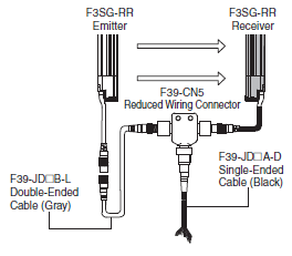
Cable for Reduce Wiring* (2 cables per set, one for emitter and one for receiver)
| Appearance | Cable length | Specifications | Remarks | Model |
|---|---|---|---|---|
 |
Emitter: 3 m Receiver: 3 m |
IP67* rated when mated. * When the accessory is used, protect it from cutting oil. |
Double-Ended Cable: F39-JD3B-L Single-Ended Cable: F39-JD3A-D |
F39-JD0303BA |
| Emitter: 3 m Receiver: 7 m |
Double-Ended Cable: F39-JD3B-L Single-Ended Cable: F39-JD7A-D |
F39-JD0307BA | ||
| Emitter: 3 m Receiver: 10 m |
Double-Ended Cable: F39-JD3B-L Single-Ended Cable: F39-JD10A-D |
F39-JD0310BA | ||
| Emitter: 5 m Receiver: 3 m |
Double-Ended Cable: F39-JD5B-L Single-Ended Cable: F39-JD3A-D |
F39-JD0503BA | ||
| Emitter: 5 m Receiver: 7 m |
Double-Ended Cable: F39-JD5B-L Single-Ended Cable: F39-JD7A-D |
F39-JD0507BA | ||
| Emitter: 5 m Receiver: 10 m |
Double-Ended Cable: F39-JD5B-L Single-Ended Cable: F39-JD10A-D |
F39-JD0510BA | ||
| Emitter: 10 m Receiver: 3 m |
Double-Ended Cable: F39-JD10B-L Single-Ended Cable: F39-JD3A-D |
F39-JD1003BA | ||
| Emitter: 10 m Receiver: 7 m |
Double-Ended Cable: F39-JD10B-L Single-Ended Cable: F39-JD7A-D |
F39-JD1007BA | ||
| Emitter: 10 m Receiver: 10 m |
Double-Ended Cable: F39-JD10B-L Single-Ended Cable: F39-JD10A-D |
F39-JD1010BA |
Note: A combination of emitter and receiver cables of other lengths than the above is also available. For details, contact your Omron representative.
* Double-Ended Cable for emitter and Single-Ended Cable for receiver.
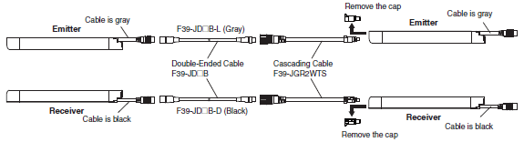
Cascading Cable (2 cables per set, one for emitter and one for receiver)
| Appearance | Type | Cable length | Specifications | Model |
|---|---|---|---|---|
 |
Cap (8-pin), M12 connector (8-pin) |
0.2 m |  IP67* rated when mated. * When the accessory is used, protect it from cutting oil. |
F39-JGR2WTS |
Note: The Double-Ended Cable (up to 10 m: F39-JD10B) can be added to extend the cable length between the series-connected sensors.
Cable length between sensors: 10 m max. (not including cascading cable (F39-JGR2WTS) and power cable)
Sensor Mounting Brackets
| Appearance | Specifications | Application | Model |
|---|---|---|---|
 |
Free-Location Bracket (Intermediate Bracket) |
Beam alignment after mounting possible. The angle adjustment range is ±15°. Side mounting and backside mounting possible. (Sold separately as a set of 2 brackets. Refer to note *1 for the number of sets required for each model.) |
F39-LGRA |
 |
Top/Bottom Bracket *2 |
Use this bracket at the top and bottom positions of the F3SG-RR. Beam alignment after mounting possible. The angle adjustment range is ±22.5°. Side mounting and backside mounting possible. (Sold separately as a set of 4 brackets.) |
F39-LGRTB |
 |
Top/Bottom Bracket *2 |
The part of this bracket to contact with a wall surface has a different shape from the F39-LGRTB Top/Bottom Bracket. Use this bracket when replacing an existing safety light curtain with the F3SG-RR. (Sold separately as a set of 4 brackets.) Select a bracket that fit into the existing mounting hole. |
F39-LGRTB-2 |
 |
Top/Bottom Bracket *2 |
F39-LGRTB-3 |
*1. Protective height of 0240 to 1200 mm: 2 sets, Protective height of 1280 to 1920 mm: 3 sets
*2. Use the Top/Bottom Bracket in combination with the Intermediate Bracket.
Protective height of 1040 or less: The Intermediate Bracket is not required. Please purchase 1 set of Top/Bottom Brackets (F39-LGRTB(-2/-3)).
Protective height of 1120 to 1920:Please purchase 1 set of Top/Bottom Brackets (F39-LGRTB(-2/-3)) and 1 set of Intermediate Brackets (F39- LGRA).
Interface units and configuration tool SD Manager 2
| Appearance | Type | Specifications | Model |
|---|---|---|---|
 |
SD Manager 2 | The Configuration Tool SD Manager 2 is available to download from our website at http://www.ia.omron.com/f3sg-r_tool |
- |
 |
Interface Unit | F39-GIF-1 interface unit to connect the F3SG-RR receiver to a USB port of the PC Accessories: F39-CN1 Branch Connector (1), Connector Cap (1), 2-m Dedicated Cable (1), Instruction Manual |
F39-GIF-1 |
 |
Bluetooth Communication Unit |
F39-BT bluetooth unit to enable bluetooth on the F3SG-RR IP67 rated when mated. |
F39-BT |
* When the accessory is used, protect it from cutting oil.
Lamp *
| Appearance | Type | Specifications | Model |
|---|---|---|---|
 |
Lamp | The lamp unit can be connected to a receiver and turned ON based on the operation of F3SG-RA/RR. The lamp can indicate red, orange, and green colors, to which three different states can be assigned. IP67 rated when mated. |
F39-LP |
| Lamp and Bluetooth Communication Unit |
F39-BTLP |
* When the accessory is used, protect it from cutting oil.
End Cap *1 *2
| Appearance | Specifications | Model |
|---|---|---|
 |
Housing color: Black For both emitter and receiver (Attached to the F3SG-RR. The End Cap can be purchased if lost.) IP67 rated when mated. |
F39-CNM |
*1. This accessory can also be used with the F3SG-RA.
*2. When the accessory is used, protect it from cutting oil.
Laser Pointer for F3SG-R *
| Appearance | Specifications | Model |
|---|---|---|
 |
The laser pointer is attached on the optical surface of the F3SG-R to help coarse adjustment of beams. |
F39-PTG |
* When the accessory is used, protect it from cutting oil.
Test Rod
| Diameter | Model |
|---|---|
| 14 mm dia. | F39-TRD14 |
| 25 mm dia. | F39-TRD25 |
F3SG-RE Easy type
Main Units
Safety Light Curtain
Finger protection
| Number of beams | Protective height (mm) | Model | |
|---|---|---|---|
| PNP output | NPN output | ||
| 15 | 160 | F3SG-4RE0160P14 | F3SG-4RE0160N14 |
| 23 | 240 | F3SG-4RE0240P14 | F3SG-4RE0240N14 |
| 31 | 320 | F3SG-4RE0320P14 | F3SG-4RE0320N14 |
| 39 | 400 | F3SG-4RE0400P14 | F3SG-4RE0400N14 |
| 47 | 480 | F3SG-4RE0480P14 | F3SG-4RE0480N14 |
| 55 | 560 | F3SG-4RE0560P14 | F3SG-4RE0560N14 |
| 63 | 640 | F3SG-4RE0640P14 | F3SG-4RE0640N14 |
| 71 | 720 | F3SG-4RE0720P14 | F3SG-4RE0720N14 |
| 79 | 800 | F3SG-4RE0800P14 | F3SG-4RE0800N14 |
| 87 | 880 | F3SG-4RE0880P14 | F3SG-4RE0880N14 |
| 95 | 960 | F3SG-4RE0960P14 | F3SG-4RE0960N14 |
| 103 | 1,040 | F3SG-4RE1040P14 | F3SG-4RE1040N14 |
| 111 | 1,120 | F3SG-4RE1120P14 | F3SG-4RE1120N14 |
| 119 | 1,200 | F3SG-4RE1200P14 | F3SG-4RE1200N14 |
| 127 | 1,280 | F3SG-4RE1280P14 | F3SG-4RE1280N14 |
| 135 | 1,360 | F3SG-4RE1360P14 | F3SG-4RE1360N14 |
| 143 | 1,440 | F3SG-4RE1440P14 | F3SG-4RE1440N14 |
| 151 | 1,520 | F3SG-4RE1520P14 | F3SG-4RE1520N14 |
| 159 | 1,600 | F3SG-4RE1600P14 | F3SG-4RE1600N14 |
| 167 | 1,680 | F3SG-4RE1680P14 | F3SG-4RE1680N14 |
| 175 | 1,760 | F3SG-4RE1760P14 | F3SG-4RE1760N14 |
| 183 | 1,840 | F3SG-4RE1840P14 | F3SG-4RE1840N14 |
| 191 | 1,920 | F3SG-4RE1920P14 | F3SG-4RE1920N14 |
| 199 | 2,000 | F3SG-4RE2000P14 | F3SG-4RE2000N14 |
| 207 | 2,080 | F3SG-4RE2080P14 | F3SG-4RE2080N14 |
Hand and arm protection
| Number of beams | Protective height (mm) | Model | |
|---|---|---|---|
| PNP | NPN | ||
| 8 | 190 | F3SG-4RE0190P30 | F3SG-4RE0190N30 |
| 12 | 270 | F3SG-4RE0270P30 | F3SG-4RE0270N30 |
| 16 | 350 | F3SG-4RE0350P30 | F3SG-4RE0350N30 |
| 20 | 430 | F3SG-4RE0430P30 | F3SG-4RE0430N30 |
| 24 | 510 | F3SG-4RE0510P30 | F3SG-4RE0510N30 |
| 28 | 590 | F3SG-4RE0590P30 | F3SG-4RE0590N30 |
| 32 | 670 | F3SG-4RE0670P30 | F3SG-4RE0670N30 |
| 36 | 750 | F3SG-4RE0750P30 | F3SG-4RE0750N30 |
| 40 | 830 | F3SG-4RE0830P30 | F3SG-4RE0830N30 |
| 44 | 910 | F3SG-4RE0910P30 | F3SG-4RE0910N30 |
| 48 | 990 | F3SG-4RE0990P30 | F3SG-4RE0990N30 |
| 52 | 1,070 | F3SG-4RE1070P30 | F3SG-4RE1070N30 |
| 56 | 1,150 | F3SG-4RE1150P30 | F3SG-4RE1150N30 |
| 60 | 1,230 | F3SG-4RE1230P30 | F3SG-4RE1230N30 |
| 64 | 1,310 | F3SG-4RE1310P30 | F3SG-4RE1310N30 |
| 68 | 1,390 | F3SG-4RE1390P30 | F3SG-4RE1390N30 |
| 72 | 1,470 | F3SG-4RE1470P30 | F3SG-4RE1470N30 |
| 76 | 1,550 | F3SG-4RE1550P30 | F3SG-4RE1550N30 |
| 80 | 1,630 | F3SG-4RE1630P30 | F3SG-4RE1630N30 |
| 84 | 1,710 | F3SG-4RE1710P30 | F3SG-4RE1710N30 |
| 88 | 1,790 | F3SG-4RE1790P30 | F3SG-4RE1790N30 |
| 92 | 1,870 | F3SG-4RE1870P30 | F3SG-4RE1870N30 |
| 96 | 1,950 | F3SG-4RE1950P30 | F3SG-4RE1950N30 |
| 100 | 2,030 | F3SG-4RE2030P30 | F3SG-4RE2030N30 |
| 104 | 2,110 | F3SG-4RE2110P30 | F3SG-4RE2110N30 |
| 108 | 2,190 | F3SG-4RE2190P30 | F3SG-4RE2190N30 |
| 112 | 2,270 | F3SG-4RE2270P30 | F3SG-4RE2270N30 |
| 116 | 2,350 | F3SG-4RE2350P30 | F3SG-4RE2350N30 |
| 120 | 2,430 | F3SG-4RE2430P30 | F3SG-4RE2430N30 |
| 124 | 2,510 | F3SG-4RE2510P30 | F3SG-4RE2510N30 |
Accessories (Sold separately)
Safety light curtain connecting cable
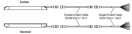
Single-Ended Cable (Round Water-resistant Connector: Connector Connected to Cable, Socket on One Cable End)
| Appearance | Type | Cable length | Specifications | Model |
|---|---|---|---|---|
 |
M12 connector (4-pin), 4 wires |
1 m |  |
XS5F-D421-C80-F |
| 2 m | XS5F-D421-D80-F | |||
| 3 m | XS5F-D421-E80-F | |||
| 5 m | XS5F-D421-G80-F | |||
| 10 m | XS5F-D421-J80-F | |||
| 20 m | XS5F-D421-L80-F |
Note:
1. One cable that can be used for both emitter and receiver is provided. Order two cables for one set of safety light curtains.
2. To extend the cable length to 20 m or more, add the XS5W-D421-[]81-F Double-Ended Cable.
Double-Ended Cable (Round Water-resistant Connector: Connectors Connected to Cable, Socket and Plug on Cable Ends)
For cable extension and simple wiring
| Appearance | Type | Cable length | Specifications | Model |
|---|---|---|---|---|
 |
M12 connector (4-pin) on both ends |
1 m |  |
XS5W-D421-C81-F |
| 2 m | XS5W-D421-D81-F | |||
| 3 m | XS5W-D421-E81-F | |||
| 5 m | XS5W-D421-G81-F | |||
| 10 m | XS5W-D421-J81-F | |||
| 20 m | XS5W-D421-L81-F |
pNote: 1. One cable that can be used for both emitter and receiver is provided. Order two cables for one set of safety light
curtains.
2. To extend the cable length to more than 20 m, add the XS5W-D421-[]81-F Double-Ended Cable to the XS5F-
D421-[]80-F Single-Ended Cable.
To extend the cable length to more than 40 m, add several Double-Ended Cables to the Single-Ended Cable.
Example: To extend the cable length to 50 m, connect two XS5W-D421-L81-F (20 m) cables and one XS5F-D421-
J80-F (10 m) cable.
Connection example
Y-Joint Plug/Socket Connector for Easy type F3SG-RE
| Appearance | Type | Cable length | Specifications | Model |
|---|---|---|---|---|
 |
M12 connectors. Used for reduced wiring. |
0.5 m |  When using the reduced wiring connector system F39-GCNY1, the Operating Range Selection is fixed to Long Mode. |
F39-GCNY1 |
Sensor Mounting Brackets
| Appearance | Specification | Application | Model |
|---|---|---|---|
|
Standard Fixed Bracket |
Bracket to mount the F3SG-R. Side mounting and backside mounting possible. (This is included as a standard accessory with the product. It comes as a set of two Brackets. Refer to note *1 for the number of sets provided with each model.) |
F39-LGF |
|
Standard Adjustable Bracket |
Bracket to mount the F3SG-R. Beam alignment after mounting possible.The angle adjustment range is ±15°. Side mounting and backside mounting possible. (Sold separately as a set of two Brackets. Refer to note *1 for the number of sets required for each model.) |
F39-LGA |
|
Top/Bottom Adjustable Bracket *2 |
Bracket to mount the F3SG-R. Use this bracket at the top and bottom positions of the F3SG-R. Beam alignment after mounting possible. The angle adjustment range is ±22.5°. Side mounting and backside mounting possible. (Sold separately. 4 brackets per set.) |
F39-LGTB |
|
Top/Bottom Adjustable Bracket *2 (For user-made mounting part) |
Top/Bottom Adjustable Bracket without a bracket to mount to the wall. Use the user's own wall mounting part to suit the machine. (Sold separately. 4 brackets per set.) |
F39-LGTB-1 |
*1. [for F3SG-4RE[][][][][]14] Protective height of 0160 to 1200: 2 sets, Protective height of 1280 to 2080: 3 sets
[for F3SG-4RE[][][][][]30] Protective height of 0190 to 1230: 2 sets, Protective height of 1310 to 2270: 3 sets,
Protective height of 2350 to 2510: 4 sets
*2. Top/Bottom Adjustable Bracket cannot be used with the Standard Fixed Bracket. Use with the Standard Adjustable
Bracket.
Using Top/Bottom Adjustable Brackets with Standard Adjustable Brackets
F3SG-4RE[][][][]-14:
Protective height of 1040 or less:
The Standard Adjustable Bracket is not required.
Please purchase 1 set of Top/Bottom Adjustable Brackets (F39-LGTB(-1)).
Protective height of 1120 to 1920:
Please purchase 1 set of Top/Bottom Adjustable Brackets (F39-LGTB(-1)) and 1 set of Standard Adjustable
Brackets (F39-LGA).
Protective height of 2000 to 2080:
Please purchase 1 set of Top/Bottom Adjustable Brackets (F39-LGTB(-1)) and 2 sets of Standard Adjustable
Brackets (F39-LGA).
F3SG-4RE[][][][]-30:
Protective height of 1070 or less:
The Standard Adjustable Bracket is not required.
Please purchase 1 set of Top/Bottom Adjustable Brackets (F39-LGTB(-1)).
Protective height of 1150 to 1950:
Please purchase 1 set of Top/Bottom Adjustable Brackets (F39-LGTB(-1)) and 1 set of Standard Adjustable
Brackets (F39-LGA).
Protective height of 2030 to 2510:
Please purchase 1 set of Top/Bottom Adjustable Brackets (F39-LGTB(-1)) and 2 sets of Standard Adjustable
Brackets (F39-LGA).
Laser Pointer for F3SG-R
| Appearance | Specifications | Model |
|---|---|---|
|
The laser pointer is attached on the optical surface of the F3SG-R to help coarse adjustment of beams. |
F39-PTG |
Spatter Protection Cover (2 covers per set, one for emitter and one for receiver)
Spatter Protection Covers include the mounting brackets
For Safety Light Curtain models of the protective height of 2,000 mm or longer, use two Spatter Protection Covers of different lengths.
| Appearance | Safety Light Curtain Model | Model | |
|---|---|---|---|
| Finger protection | Hand and arm protection | ||
 |
F3SG-4RE0160[]14 | F3SG-4RE0190[]30 | F39-HGB0180 |
| F3SG-4RE0240[]14 | F3SG-4RE0270[]30 | F39-HGB0260 | |
| F3SG-4RE0320[]14 | F3SG-4RE0350[]30 | F39-HGB0340 | |
| F3SG-4RE0400[]14 | F3SG-4RE0430[]30 | F39-HGB0420 | |
| F3SG-4RE0480[]14 | F3SG-4RE0510[]30 | F39-HGB0500 | |
| F3SG-4RE0560[]14 | F3SG-4RE0590[]30 | F39-HGB0580 | |
| F3SG-4RE0640[]14 | F3SG-4RE0670[]30 | F39-HGB0660 | |
| F3SG-4RE0720[]14 | F3SG-4RE0750[]30 | F39-HGB0740 | |
| F3SG-4RE0800[]14 | F3SG-4RE0830[]30 | F39-HGB0820 | |
| F3SG-4RE0880[]14 | F3SG-4RE0910[]30 | F39-HGB0900 | |
| F3SG-4RE0960[]14 | F3SG-4RE0990[]30 | F39-HGB0980 | |
| F3SG-4RE1040[]14 | F3SG-4RE1070[]30 | F39-HGB1060 | |
| F3SG-4RE1120[]14 | F3SG-4RE1150[]30 | F39-HGB1140 | |
| F3SG-4RE1200[]14 | F3SG-4RE1230[]30 | F39-HGB1220 | |
| F3SG-4RE1280[]14 | F3SG-4RE1310[]30 | F39-HGB1300 | |
| F3SG-4RE1360[]14 | F3SG-4RE1390[]30 | F39-HGB1380 | |
| F3SG-4RE1440[]14 | F3SG-4RE1470[]30 | F39-HGB1460 | |
| F3SG-4RE1520[]14 | F3SG-4RE1550[]30 | F39-HGB1540 | |
| F3SG-4RE1600[]14 | F3SG-4RE1630[]30 | F39-HGB1620 | |
| F3SG-4RE1680[]14 | F3SG-4RE1710[]30 | F39-HGB1700 | |
| F3SG-4RE1760[]14 | F3SG-4RE1790[]30 | F39-HGB1780 | |
| F3SG-4RE1840[]14 | F3SG-4RE1870[]30 | F39-HGB1860 | |
| F3SG-4RE1920[]14 | F3SG-4RE1950[]30 | F39-HGB1940 | |
| F3SG-4RE2000[]14 | F3SG-4RE2030[]30 | F39-HGB1460 | |
| F39-HGA0550 | |||
| F3SG-4RE2080[]14 | F3SG-4RE2110[]30 | F39-HGB1540 | |
| F39-HGA0550 | |||
| - | F3SG-4RE2190[]30 | F39-HGB1620 | |
| F39-HGA0550 | |||
| - | F3SG-4RE2270[]30 | F39-HGB1700 | |
| F39-HGA0550 | |||
| - | F3SG-4RE2350[]30 | F39-HGB1780 | |
| F39-HGA0550 | |||
| - | F3SG-4RE2430[]30 | F39-HGB1860 | |
| F39-HGA0550 | |||
| - | F3SG-4RE2510[]30 | F39-HGB1940 | |
| F39-HGA0550 | |||
Note: The operating range of the Safety Light Curtain attached with the product is 10% shorter than the rating.
Test Rod
| Diameter | Model |
|---|---|
| 14 mm dia. | F39-TRD14 |
| 30 mm dia. | F39-TRD30 |
F3SG-RA-01TS
Main Units
Safety Light Curtain
Hand and arm protection
| Number of beams | Protective height (mm) | Model |
|---|---|---|
| 8 | 185 | F3SG-4RA0185-25-01TS |
| 12 | 265 | F3SG-4RA0265-25-01TS |
| 16 | 345 | F3SG-4RA0345-25-01TS |
| 20 | 425 | F3SG-4RA0425-25-01TS |
| 24 | 505 | F3SG-4RA0505-25-01TS |
| 28 | 585 | F3SG-4RA0585-25-01TS |
| 32 | 665 | F3SG-4RA0665-25-01TS |
| 36 | 745 | F3SG-4RA0745-25-01TS |
| 40 | 825 | F3SG-4RA0825-25-01TS |
| 44 | 905 | F3SG-4RA0905-25-01TS |
| 48 | 985 | F3SG-4RA0985-25-01TS |
| 52 | 1,065 | F3SG-4RA1065-25-01TS |
| 56 | 1,145 | F3SG-4RA1145-25-01TS |
| 60 | 1,225 | F3SG-4RA1225-25-01TS |
| 64 | 1,305 | F3SG-4RA1305-25-01TS |
| 68 | 1,385 | F3SG-4RA1385-25-01TS |
| 72 | 1,465 | F3SG-4RA1465-25-01TS |
| 76 | 1,545 | F3SG-4RA1545-25-01TS |
| 80 | 1,625 | F3SG-4RA1625-25-01TS |
| 84 | 1,705 | F3SG-4RA1705-25-01TS |
| 88 | 1,785 | F3SG-4RA1785-25-01TS |
| 92 | 1,865 | F3SG-4RA1865-25-01TS |
| 96 | 1,945 | F3SG-4RA1945-25-01TS |
Accessories (Sold separately)
Safety light curtain connecting cable
Single-Ended Cable (2 cables per set, one for emitter and one for receiver) *
| Appearance | Cable length | Specifications | Model |
|---|---|---|---|
 |
3m |  |
F39-JD3A |
| 7m | F39-JD7A | ||
| 10m | F39-JD10A | ||
| 15m | F39-JD15A | ||
| 20m | F39-JD20A |
* The cable for emitter and the cable for receiver are available separately. Add '-L' for emitter or '-D' for receiver to the end of the model number when you order.
Single-Ended Cable for Emitter: F39-JD[]A-L, Single-Ended Cable for Receiver: F39-JD[]A-D
Note: To extend the cable length to more than 20 m, add the F39-JD[]B Double-Ended Cable.
Doble-Ended Cable (2 cables per set, one for emitter and one for receiver) *
For cable extension
| Appearance | Cable length | Specifications | Model |
|---|---|---|---|
 |
0.5 m |  |
F39-JDR5B |
| 1 m | F39-JD1B | ||
| 3 m | F39-JD3B | ||
| 5 m | F39-JD5B | ||
| 7 m | F39-JD7B | ||
| 10 m | F39-JD10B | ||
| 15 m | F39-JD15B | ||
| 20 m | F39-JD20B |
* The cable for emitter and the cable for receiver are available separately. Add '-L' for emitter or '-D' for receiver to the end
of the model number when you order.
Double-Ended Cable for Emitter: F39-JD(R)[]B-L, Double-Ended Cable for Receiver: F39-JD(R)[]B-D
Note: To extend the cable length to more than 20 m, add the F39-JD[]B Double-Ended Cable to the F39-JD[]A Single-
Ended Cable.
To extend the cable length to more than 40 m, add several Double-Ended Cables to the Single-Ended Cable.
Example: To extend the cable length to 50 m, connect two F39-JD20B (20 m) cables and one F39-JD10A (10 m)
cable.
Connection example
Cascading Cable (2 cables per set, for emitter and receiver)
| Appearance | Type | Cable length | Specifications | Model |
|---|---|---|---|---|
 |
Cap (8-pin), M12 connector (8-pin) |
0.2m |  |
F39-JGR2WTS |
Note: The Double-Ended Cable (up to 10 m: F39-JD10B) can be added to extend the cable length between the series-connected sensors. Cable length between sensors: 10 m max. (not including cascading cable (F39-JGR2WTS) and power cable)
Connection example
Reduced Wiring Connector System (Order the F39-CN5 and Cables for Reduce Wiring.)
Reduced Wiring Connector
| Appearance | Specifications | Model |
|---|---|---|
 |
IP67 rated when mated. | F39-CN5 |
Note: When using the Reduced Wiring Connector (F39-CN5), the following functions are not available.
- External Device Monitoring
- Auxiliary Output
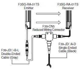
Cable for Reduce Wiring* (2 cables per set, one for emitter and one for receiver)
| Appearance | Cable length | Specifications | Remarks | Model |
|---|---|---|---|---|
 |
Emitter: 3 m Receiver: 3 m |
IP67 rated when mated. |
Double-Ended Cable: F39-JD3B-L Single-Ended Cable: F39-JD3A-D |
F39-JD0303BA |
| Emitter: 3 m Receiver: 7 m |
Double-Ended Cable: F39-JD3B-L Single-Ended Cable: F39-JD7A-D |
F39-JD0307BA | ||
| Emitter: 3 m Receiver: 10 m |
Double-Ended Cable: F39-JD3B-L Single-Ended Cable: F39-JD10A-D |
F39-JD0310BA | ||
| Emitter: 5 m Receiver: 3 m |
Double-Ended Cable: F39-JD5B-L Single-Ended Cable: F39-JD3A-D |
F39-JD0503BA | ||
| Emitter: 5 m Receiver: 7 m |
Double-Ended Cable: F39-JD5B-L Single-Ended Cable: F39-JD7A-D |
F39-JD0507BA | ||
| Emitter: 5 m Receive: 10m |
Double-Ended Cable: F39-JD5B-L Single-Ended Cable: F39-JD10A-D |
F39-JD0510BA | ||
| Emitter: 10 m Receiver: 3 m |
Double-Ended Cable: F39-JD10B-L Single-Ended Cable: F39-JD3A-D |
F39-JD1003BA | ||
| Emitter: 10 m Receiver: 7 m |
Double-Ended Cable: F39-JD10B-L Single-Ended Cable: F39-JD7A-D |
F39-JD1007BA | ||
| Emitter: 10 m Receiver: 10 m |
Double-Ended Cable: F39-JD10B-L Single-Ended Cable: F39-JD10A-D |
F39-JD1010BA |
Note: A combination of emitter and receiver cables of other lengths than the above is also available. For details, contact your Omron representative.
* Double-Ended Cable for emitter and Single-Ended Cable for receiver.
Sensor Mounting Brackets
| Appearance | Specification | Application | Model |
|---|---|---|---|
 |
Standard Fixed Bracket |
Bracket to mount the F3SG-RA-01TS. Side mounting and backside mounting possible. (Sold separately as a set of two Brackets. Refer to note *1 for the number of sets required for each model.) |
F39-LGF |
 |
Standard Adjustable Bracket |
Bracket to mount the F3SG-RA-01TS. Beam alignment after mounting possible. The angle adjustment range is ±15°. Side mounting and backside mounting possible. (Sold separately as a set of two Brackets. Refer to note *1 for the number of sets required for each model.) |
F39-LGA |
 |
Top/Bottom Adjustable Bracket *2 |
Bracket to mount the F3SG-RA-01TS. Use this bracket at the top and bottom positions of the F3SG-RA-01TS. Beam alignment after mounting possible. The angle adjustment range is ±22.5°. Side mounting and backside mounting possible. (Sold separately. 4 brackets per set.) |
F39-LGTB |
 |
Top/Bottom Adjustable Bracket *2 (For user-made mounting part) |
Top/Bottom Adjustable Bracket without a bracket to mount to the wall. Use the user's own wall mounting part to suit the machine. (Sold separately. 4 brackets per set.) |
F39-LGTB-1 |
*1. Protective height of 0185 to 1225: 2 sets, Protective height of 1305 to 1945: 3 sets
*2. Top/Bottom Adjustable Bracket cannot be used with the Standard Fixed Bracket. Use with the Standard Adjustable
Bracket.
Using Top/Bottom Adjustable Brackets with Standard Adjustable Brackets
Protective height of 1065 or less:
The Standard Adjustable Bracket is not required.
Please purchase 1 set of Top/Bottom Adjustable Brackets (F39-LGTB(-1)).
Protective height of 1145 to 1945:
Please purchase 1 set of Top/Bottom Adjustable Brackets (F39-LGTB(-1)) and 1 set of Standard Adjustable Brackets (F39-LGA).
Interface units and configuration tool SD Manager 2 *
| Appearance | Type | Specifications | Model |
|---|---|---|---|
 |
SD Manager 2 | The Configuration Tool SD Manager 2 is available to download from our website at http://www.ia.omron.com/f3sg-r_tool. |
- |
 |
Interface Unit | F39-GIF interface unit to connect the F3SG-RA-01TS receiver to a USB port of the PC Accessories: 0.3-m Dedicated Cable 1 (1), 2-m Dedicated Cable 2 (1), Instruction Manual |
F39-GIF |
 |
Bluetooth Communication Unit |
F39-BT bluetooth unit to enable bluetooth on the F3SG-RA IP67 rated when mated. |
F39-BT |
* The F3SG-RA-01TS provides only the monitoring functionality.
Lamp
| Appearance | Type | Specifications | Model |
|---|---|---|---|
 |
Lamp unit | The lamp can be connected to a receiver and turned ON based on the operation of F3SG-RA. The lamp output pattern is set as follows: Red (ON): Inverted signal of safety output information Orange (Blink once): Inverted signal of stable-state information Green (ON): Safety output information IP67 rated when mated. |
F39-LP |
| Lamp and Bluetooth Communication Unit |
F39-BTLP |
End Cap *
| Appearance | Specifications | Model |
|---|---|---|
 |
Housing color: Black For both emitter and receiver (Attached to the F3SG-RA-01TS. The End Cap can be purchased if lost.) IP67 rated when mated. |
F39-CNM |
* This accessory can also be used with the F3SG-RA-02TS.
Laser Pointer for F3SG-R
| Appearance | Specifications | Model |
|---|---|---|
 |
The laser pointer is attached on the optical surface of the F3SG-R to help coarse adjustment of beams. |
F39-PTG |
Spatter Protection Cover (2 covers per set, one for emitter and one for receiver)
Spatter Protection Covers include mounting brackets.
| Appearance | Safety Light Curtain Model | Model |
|---|---|---|
| Hand protection | ||
 |
F3SG-4RA0185-25-01TS | F39-HGA0200 |
| F3SG-4RA0265-25-01TS | F39-HGA0280 | |
| F3SG-4RA0345-25-01TS | F39-HGA0360 | |
| F3SG-4RA0425-25-01TS | F39-HGA0440 | |
| F3SG-4RA0505-25-01TS | F39-HGA0520 | |
| F3SG-4RA0585-25-01TS | F39-HGA0600 | |
| F3SG-4RA0665-25-01TS | F39-HGA0680 | |
| F3SG-4RA0745-25-01TS | F39-HGA0760 | |
| F3SG-4RA0825-25-01TS | F39-HGA0840 | |
| F3SG-4RA0905-25-01TS | F39-HGA0920 | |
| F3SG-4RA0985-25-01TS | F39-HGA1000 | |
| F3SG-4RA1065-25-01TS | F39-HGA1080 | |
| F3SG-4RA1145-25-01TS | F39-HGA1160 | |
| F3SG-4RA1225-25-01TS | F39-HGA1240 | |
| F3SG-4RA1305-25-01TS | F39-HGA1320 | |
| F3SG-4RA1385-25-01TS | F39-HGA1400 | |
| F3SG-4RA1465-25-01TS | F39-HGA1480 | |
| F3SG-4RA1545-25-01TS | F39-HGA1560 | |
| F3SG-4RA1625-25-01TS | F39-HGA1640 | |
| F3SG-4RA1705-25-01TS | F39-HGA1720 | |
| F3SG-4RA1785-25-01TS | F39-HGA1800 | |
| F3SG-4RA1865-25-01TS | F39-HGA1880 | |
| F3SG-4RA1945-25-01TS | F39-HGA1960 |
Note:
1. The operating range of the Safety Light Curtain attached with the product is 10% shorter than the rating.
2. The product extends over the DIP Switch cover of the Safety Light Curtain. Be sure to use the product only after all required settings are made to the DIP Switch.
Test Rod
| Diameter | Model |
|---|---|
| 25 mm dia. | F39-TRD25 |
F3SG-RA-02TS
Main Units
Safety Light Curtain
Hand and arm protection
| Number of beams | Protective height (mm) | Model |
|---|---|---|
| 12 | 240 | F3SG-4RA0240-25-02TS |
| 16 | 320 | F3SG-4RA0320-25-02TS |
| 20 | 400 | F3SG-4RA0400-25-02TS |
| 24 | 480 | F3SG-4RA0480-25-02TS |
| 28 | 560 | F3SG-4RA0560-25-02TS |
| 32 | 640 | F3SG-4RA0640-25-02TS |
| 36 | 720 | F3SG-4RA0720-25-02TS |
| 40 | 800 | F3SG-4RA0800-25-02TS |
| 44 | 880 | F3SG-4RA0880-25-02TS |
| 48 | 960 | F3SG-4RA0960-25-02TS |
| 52 | 1,040 | F3SG-4RA1040-25-02TS |
| 56 | 1,120 | F3SG-4RA1120-25-02TS |
| 60 | 1,200 | F3SG-4RA1200-25-02TS |
| 64 | 1,280 | F3SG-4RA1280-25-02TS |
| 68 | 1,360 | F3SG-4RA1360-25-02TS |
| 72 | 1,440 | F3SG-4RA1440-25-02TS |
| 76 | 1,520 | F3SG-4RA1520-25-02TS |
| 80 | 1,600 | F3SG-4RA1600-25-02TS |
| 84 | 1,680 | F3SG-4RA1680-25-02TS |
| 88 | 1,760 | F3SG-4RA1760-25-02TS |
| 92 | 1,840 | F3SG-4RA1840-25-02TS |
| 96 | 1,920 | F3SG-4RA1920-25-02TS |
Accessories (Sold separately)
Safety light curtain connecting cable
Single-Ended Cable (Oil-Resistant Cable)
| Appearance | Type | Cable length | Specifications | Model |
|---|---|---|---|---|
 |
For emitter M12 connector (8-pin), 5 wires Color: Gray |
3m |  IP67 and IP67G (JIS C 0920 Annex 1) * rated when mated. * F3SG-RA-02TS meets the degree of protection when this cable is correctly connected with the power cable of the F3SG-RA-02TS. The degree of protection is not satisfied with the part where cable wires are uncovered. |
F39-JD3RA-L |
| 7m | F39-JD7RA-L | |||
| For receiver M12 connector (8-pin), 8 wires Color: Black |
3m | F39-JD3RA-D | ||
| 7m | F39-JD7RA-D |
Note: To extend the cable length to more than 7 m, add the F39-JD[]B Double-Ended Cable.
When the Double-Ended Cable is used, protect it from cutting oil.
Single-Ended Cable (2 cables per set, one for emitter and one for receiver) *
| Appearance | Cable length | Specifications | Model |
|---|---|---|---|
 |
3m |  IP67* rated when mated. * When the accessory is used, protect it from cutting oil. |
F39-JD3A |
| 7m | F39-JD7A | ||
| 10m | F39-JD10A | ||
| 15m | F39-JD15A | ||
| 20m | F39-JD20A |
* The cable for emitter and the cable for receiver are available separately. Add '-L' for emitter or '-D' for receiver to the end of the model number when you order.
Single-Ended Cable for Emitter: F39-JD[]A-L, Single-Ended Cable for Receiver: F39-JD[]A-D
Note:
1. Use the F39-JD[]RA-L/-D for applications where cutting oil resistance is required.
2. To extend the cable length to more than 20 m, add the F39-JD[]B Double-Ended Cable.
Double-Ended Cable (2 cables per set, one for emitter and one for receiver) *
| Appearance | Cable length | Specifications | Model |
|---|---|---|---|
 |
0.5m |  IP67* rated when mated. * When the accessory is used, protect it from cutting oil. |
F39-JDR5B |
| 1m | F39-JD1B | ||
| 3m | F39-JD3B | ||
| 5m | F39-JD5B | ||
| 7m | F39-JD7B | ||
| 10m | F39-JD10B | ||
| 15m | F39-JD15B | ||
| 20m | F39-JD20B |
* The cable for emitter and the cable for receiver are available separately. Add '-L' for emitter or '-D' for receiver to the end
of the model number when you order.
Double-Ended Cable for Emitter: F39-JD[]B-L, Double-Ended Cable for Receiver: F39-JD[]B-D
Note: To extend the cable length to more than 20 m, add the F39-JD[]B Double-Ended Cable to the F39-JD[]A Single-
Ended Cable.
To extend the cable length to more than 40 m, add several Double-Ended Cables to the Single-Ended Cable.
Example: To extend the cable length to 50 m, connect two F39-JD20B (20 m) cables and one F39-JD10A (10 m)
cable.
Connection example
Reduced Wiring Connector System (Order the F39-CN5 and Cables for Reduce Wiring.)
Reduced Wiring Connector
| Appearance | Specifications | Model |
|---|---|---|
 |
IP67* rated when mated. * When the accessory is used, protect it from cutting oil. |
F39-CN5 |
Note: When using the Reduced Wiring Connector (F39-CN5), the following functions are not available.
- External Device Monitoring
- Auxiliary Output
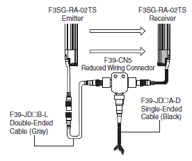
Cable for Reduce Wiring* (2 cables per set, one for emitter and one for receiver
| Appearance | Cable length | Specifications | Remarks | Model |
|---|---|---|---|---|
 |
Emitter: 3 m Receiver: 3 m |
IP67* rated when mated. * When the accessory is used, protect it from cutting oil |
Double-Ended Cable: F39-JD3B-L Single-Ended Cable: F39-JD3A-D |
F39-JD0303BA |
| Emitter: 3 m Receiver: 7 m |
Double-Ended Cable: F39-JD3B-L Single-Ended Cable: F39-JD7A-D |
F39-JD0307BA | ||
| Emitter: 3 m Receiver: 10 m |
Double-Ended Cable: F39-JD3B-L Single-Ended Cable: F39-JD10A-D |
F39-JD0310BA | ||
| Emitter: 5 m Receiver: 3 m |
Double-Ended Cable: F39-JD5B-L Single-Ended Cable: F39-JD3A-D |
F39-JD0503BA | ||
| Emitter: 5 m Receiver: 7 m |
Double-Ended Cable: F39-JD5B-L Single-Ended Cable: F39-JD7A-D |
F39-JD0507BA | ||
| Emitter: 5 m Receiver: 10 m |
Double-Ended Cable: F39-JD5B-L Single-Ended Cable: F39-JD10A-D |
F39-JD0510BA | ||
| Emitter: 10 m Receiver: 3 m |
Double-Ended Cable: F39-JD10B-L Single-Ended Cable: F39-JD3A-D |
F39-JD1003BA | ||
| Emitter: 10 m Receiver: 7 m |
Double-Ended Cable: F39-JD10B-L Single-Ended Cable: F39-JD7A-D |
F39-JD1007BA | ||
| Emitter: 10 m Receiver: 10 m |
Double-Ended Cable: F39-JD10B-L Single-Ended Cable: F39-JD10A-D |
F39-JD1010BA |
Note: A combination of emitter and receiver cables of other lengths than the above is also available. For details, contact your Omron representative.
* Double-Ended Cable for emitter and Single-Ended Cable for receiver.
Cascading Cable (2 cables per set, one for emitter and one for receiver)
| Appearance | Type | Cable length | Specifications | Model |
|---|---|---|---|---|
 |
Cap (8-pin), M12 connector (8-pin) |
0.2m |  * When the accessory is used, protect it from cutting oil. |
F39-JGR2WTS |
Note: The Double-Ended Cable (up to 10 m: F39-JD10B) can be added to extend the cable length between the series-connected sensors.
Cable length between sensors: 10 m max. (not including cascading cable (F39-JGR2WTS) and power cable)
Sensor Mounting Brackets
| Appearance | Specifications | Application | Model |
|---|---|---|---|
 |
Free-Location Bracket (Intermediate Bracket) |
Beam alignment after mounting possible. The angle adjustment range is ±15°. Side mounting and backside mounting possible. (Sold separately as a set of 2 brackets. Refer to note *1 for the number of sets required for each model.) |
F39-LGRA |
 |
Top/Bottom Bracket *2 |
Use this bracket at the top and bottom positions of the F3SG-RA-02TS. Beam alignment after mounting possible. The angle adjustment range is ±22.5°. Side mounting and backside mounting possible. (Sold separately as a set of 4 brackets.) |
F39-LGRTB |
 |
Top/Bottom Bracket *2 |
The part of this bracket to contact with a wall surface has a different shape from the F39-LGRTB Top/Bottom Bracket. Use this bracket when replacing an existing safety light curtain with the F3SG-RA-02TS. (Sold separately as a set of 4 brackets.) Select a bracket that fit into the existing mounting hole. |
F39-LGRTB-2 |
 |
Top/Bottom Bracket *2 |
F39-LGRTB-3 |
*1. Protective height of 0240 to 1200 mm: 2 sets, Protective height of 1280 to 1920 mm: 3 sets
*2. Use the Top/Bottom Bracket in combination with the Intermediate Bracket.
Protective height of 1040 or less:
The Intermediate Bracket is not required. Please purchase 1 set of Top/Bottom Brackets (F39-LGRTB(-2/-3)).
Protective height of 1120 to 1920:
Please purchase 1 set of Top/Bottom Brackets (F39-LGRTB(-2/-3)) and 1 set of Intermediate Brackets (F39-LGRA).
Interface units and configuration tool SD Manager 2 *1 *2
| Appearance | Type | Specifications | Model |
|---|---|---|---|
 |
SD Manager 2 | The Configuration Tool SD Manager 2 is available to download from our website at http://www.ia.omron.com/f3sg-r_tool |
- |
 |
Interface Unit | F39-GIF-1 interface unit to connect the F3SG-RA-02TS receiver to a USB port of the PC Accessories: F39-CN1 Branch Connector (1), Connector Cap (1), 2-m Dedicated Cable (1), Instruction Manual |
F39-GIF-1 |
 |
Bluetooth Communication Unit |
F39-BT bluetooth unit to enable bluetooth on the F3SG-RA IP67 rated when mated. |
F39-BT |
*1. The F3SG-RA-02TS provides only the monitoring functionality.
*2. When the accessory is used, protect it from cutting oil.
Lamp *
| Appearance | Type | 仕様 | Model |
|---|---|---|---|
 |
Lamp | The lamp can be connected to a receiver and turned ON based on the operation of F3SG-RA. The lamp output pattern is set as follows: Red (ON): Inverted signal of safety output information Orange (Blink once): Inverted signal of stable-state information Green (ON): Safety output information IP67 rated when mated. |
F39-LP |
| Lamp and Bluetooth Communication Unit |
F39-BTLP |
* When the accessory is used, protect it from cutting oil.
End Cap *1 *2
| Appearance | Specifications | Model |
|---|---|---|
 |
Housing color: Black For both emitter and receiver (Attached to the F3SG-RA-02TS. The End Cap can be purchased if lost.) IP67 rated when mated. |
F39-CNM |
*1. This accessory can also be used with the F3SG-RA-01TS.
*2. When the accessory is used, protect it from cutting oil.
Laser Pointer for F3SG-R *
| Appearance | Specifications | Model |
|---|---|---|
 |
The laser pointer is attached on the optical surface of the F3SG-R to help coarse adjustment of beams. |
F39-PTG |
* When the accessory is used, protect it from cutting oil.
Test Rod
| Diameter | Model |
|---|---|
| 25 mm dia. | F39-TRD25 |
Specifications| Safety Light Curtain - F3SG-R series series
last update: November 1, 2018
F3SG-RA Advanced type
Main unit
The [][][][] in the model names indicate the protective heights in millimeters.
| F3SG-4RA[][][][]-14 F3SG-2RA[][][][]-14 | F3SG-4RA[][][][]-30 F3SG-2RA[][][][]-30 | |||
|---|---|---|---|---|
| Type of ESPE (IEC 61496-1) | Type 4 | F3SG-4RA[][][][]-14/-30 | ||
| Type 2 | F3SG-2RA[][][][]-14/-30 | |||
| Perfor- mance | Object Resolution (Detection Capability) |
Opaque objects | ||
| 14-mm dia. | 30-mm dia. | |||
| Beam Gap | 10 mm | 20 mm | ||
| Number of Beams | 15 to 207 | 8 to 124 | ||
| Lens Size | 5.2 × 3.4 (W × H) mm | 7-mm dia. | ||
| Protective Height | 160 to 2080 mm (6.3 to 81.9 inch) | 190 to 2510 mm (7.3 to 98.7 inch) | ||
| Operating Range | Long | 0.3 to 10.0 m (1 to 32 ft.) | 0.3 to 20.0 m (1 to 65 ft.) | |
| Short | 0.3 to 3.0 m (1 to 10 ft.) | 0.3 to 7.0 m (1 to 23 ft.) | ||
| Response Time | ON to OFF | Normal mode: 8 to 18 ms max. *1 Slow mode: 16 to 36 ms max. *1 *2 |
||
| OFF to ON | 40 to 90 ms max. *1 | |||
| *1. Response time when used in one segment system or in cascaded connection. Refer to the one segment system. Refer to Safety Light Curtain F3SG-R Series User's Manual (ManNo.: Z352) for cascaded connection. *2. Selectable by Configuration Tool. |
||||
| Effective Aperture Angle (EAA) (IEC 61496-2) | Type 4 | ±2.5° max., emitter and receiver at operating range of 3 m or greater | ||
| Type 2 | ±5.0° max., emitter and receiver at operating range of 3 m or greater | |||
| Light Source | Infrared LEDs, Wavelength: 870 nm | |||
| Startup Waiting Time | 2 s max. | |||
| Elec- trical | Power Supply Voltage (Vs) | SELV/PELV 24 VDC±20% (ripple p-p 10% max.) | ||
| Current Consumption | Refer to "List of Models/Response Time/Current Consumption/Weight". | |||
| Safety Outputs (OSSD) | Two PNP or NPN transistor outputs (PNP or NPN is selectable by DIP Switch.) Load current of 300 mA max., Residual voltage of 2 V max. (except for voltage drop due to cable extension), Capacitive load of 1 μF max., Inductive load of 2.2 H max. *1 Leakage current of 1 mA max. (PNP), 2 mA max. (NPN) *2 *1 The load inductance is the maximum value when the safety output frequently repeats ON and OFF. When you use the safety output at 4 Hz or less, the usable load inductance becomes larger. *2 These values must be taken into consideration when connecting elements including a capacitive load such as a capacitor. |
|||
| Auxiliary Output | One PNP or NPN transistor output (PNP or NPN is selectable by DIP Switch.) Load current of 100 mA max., Residual voltage of 2 V max . |
|||
| Output Operation Mode | Safety Output | Light-ON (Safety output is enabled when the receiver receives an emitting signal.) |
||
| Auxiliary Output | Safety output (Inverted signal output:Enable) (default) (Cofigurable by Configuration Tool) |
|||
| Input Voltage | ON Voltage | TEST: 24 V Active: 9 V to Vs (sink current 3 mA max.) * 0 V Active: 0 to 3 V (source current 3 mA max.) MUTE A/B: PNP: Vs to Vs-3 V (sink current 3 mA max.) * NPN: 0 to 3 V (source current 3 mA max.) RESET: PNP: Vs to Vs-3 V (sink current 5 mA max.) * NPN: 0 to 3 V (source current 5 mA max.) |
||
| OFF Voltage | TEST: 24 V Active: 0 to 1.5 V or open 0 V Active: 9 V to Vs or open MUTE A/B, RESET: PNP: 0 to 1/2 Vs, or open * NPN: 1/2 Vs to Vs, or open * |
|||
| * The Vs indicates a supply voltage value in your environment. | ||||
| Overvoltage Category (IEC 60664-1) |
II | |||
| Indicators | Refer to "Indicator". | |||
| Protective Circuit | Output short protection, Power supply reverse polarity protection | |||
| Insulation Resistance | 20 MΩor higher (500 VDC megger) | |||
| Dielectric Strength | 1,000 VAC, 50/60 Hz (1 min) | |||
| Func- tional | Mutual Interference Prevention (Scan Code) |
This function prevents mutual interference in up to two F3SG-RA systems. |
||
| Cascade Connection | Number of cascaded segments: 3 max. Total number of beams: 255 max. Cable length between sensors: 10 m max. (not including cascading cable (F39-JGR2W) and power cable) |
|||
| Test Function | Self-test (at power-on, and during operation) External test (light emission stop function by test input) |
|||
| Safety-Related Functions | Interlock External device monitoring (EDM) Pre-reset Fixed blanking/Floating blanking Reduced resolution Muting/Override Scan code selection PNP/NPN selection Response time adjustment |
|||
| Environ- mental | Ambient Temperature | Operating | -10 to 55°C (14 to 131°F) (non-icing) | |
| Storage | -25 to 70°C (-13 to 158°F) | |||
| Ambient Humidity | Operating | 35% to 85% (non-condensing) | ||
| Storage | 35% to 95% | |||
| Ambient Illuminance | Incandescent lamp: 3,000 Ix max. on receiver surface Sunlight: 10,000 Ix max. on receiver surface |
|||
| Degree of Protection (IEC 60529) |
IP65 and IP67 | |||
| Vibration Resistance (IEC 61496-1) |
10 to 55 Hz, Multiple amplitude of 0.7 mm, 20 sweeps for all 3 axes | |||
| Shock Resistance (IEC 61496-1) |
100 m/s2, 1000 shocks for all 3 axes | |||
| Pollution Degree (IEC 60664-1) | Pollution Degree 3 | |||
| Connec- tions | Power cable | Type of Connection |
M12 connectors: 5-pin emitter and 8-pin receiver, IP67 rated when mated, Cables prewired to the sensors |
|
| Number of Wires | Emitter: 5, Receiver: 8 | |||
| Cable Length | 0.3 m | |||
| Cable Diameter | 6 mm | |||
| Minimum Bending Radius |
R5 mm | |||
| Cascading cable | Type of Connection |
M12 connectors: 5-pin emitter and 8-pin receiver, IP67 rated when mated | ||
| Number of Wires | Emitter: 5, Receiver: 8 | |||
| Cable Length | 0.2 m | |||
| Cable Diameter | 6 mm | |||
| Minimum Bending Radius |
R5 mm | |||
| Extension cable - Single- Ended Cable - Double- Ended Cable | Type of Connection |
M12 connectors: 5-pin emitter and 8-pin receiver, IP67 rated when mated | ||
| Number of Wires | Emitter: 5, Receiver: 8 | |||
| Cable Length | Refer to Lineup. | |||
| Cable Diameter | 6.6 mm | |||
| Minimum Bending Radius |
R36 mm | |||
| Extension of Power Cable | 100 m max. | |||
| Material | Material | Housing: Aluminum alloy Cap: PBT resin Front window: Acrylic resin Cable: Oil-resistant PVC resin Standard Fixed Bracket (F39-LGF): Zinc alloy FE plate: Stainless steel |
||
| Weight | Refer to "List of Models/Response Time/Current Consumption/Weight". | |||
| Included Accessories | Safety Precautions, Quick Installation Manual, Standard Fixed Bracket *, Troubleshooting Guide Sticker, Warning Zone Label * The quantity of Standard Fixed Brackets included varies depending on the protective height. [F3SG-[]RA[][][][]-14] - Protective height of 0160 to 1200: 2 sets - Protective height of 1280 to 2080: 3 sets [F3SG-[]RA[][][][]-30] - Protective height of 0190 to 1230: 2 sets - Protective height of 1310 to 2270: 3 sets - Protective height of 2350 to 2510: 4 sets |
|||
| Con- formity | Conforming standards | Refer to "Legislation and Standards". | ||
| Type of ESPE (IEC 61496-1) | Type 4 | |||
| Performance Level (PL)/ Safety category | Type 4 | PL e/Category 4 (EN ISO 13849-1:2015) | ||
| Type 2 | PL c/Category 2 (EN ISO 13849-1:2015) | |||
| PFHD | 1.1 × 10⁻⁸ (IEC 61508) | |||
| Proof test interval TM | Every 20 years (IEC 61508) | |||
| SFF | 99% (IEC 61508) | |||
| HFT | 1 (IEC 61508) | |||
| Classification | Type B (IEC 61508-2) | |||
Bluetooth Communication Unit
| Communication System | Bluetooth Version 3.0 |
|---|---|
| Communication Profile | SPP (Serial Port Profile) |
| Transmission Distance | Approx. 10 m max. (Output power: Class 2) * |
* It depends on use environment conditions.
List of Models/Response Time/Current Consumption/Weight
F3SG-4RA[][][][]-14/F3SG-2RA[][][][]-14
| Model | Num- ber of Beams | Pro- tective Height [mm] | Response Time [ms] *1 | Current Consumption [mA] | Weight [kg] | |||||
|---|---|---|---|---|---|---|---|---|---|---|
| ON → OFF *2 | OFF (Syn- chro- nized) → ON | OFF (Not syn- chro- nized) → ON | Emitter | Re- ceiver | Net *3 | Gross *4 | ||||
| F3SG-4RA0160-14 | F3SG-2RA0160-14 | 15 | 160 | 8 | 40 | 140 | 40 | 75 | 0.7 | 2.0 |
| F3SG-4RA0240-14 | F3SG-2RA0240-14 | 23 | 240 | 8 | 40 | 140 | 45 | 75 | 0.9 | 2.3 |
| F3SG-4RA0320-14 | F3SG-2RA0320-14 | 31 | 320 | 8 | 40 | 140 | 55 | 75 | 1.1 | 2.6 |
| F3SG-4RA0400-14 | F3SG-2RA0400-14 | 39 | 400 | 8 | 40 | 140 | 60 | 80 | 1.3 | 2.9 |
| F3SG-4RA0480-14 | F3SG-2RA0480-14 | 47 | 480 | 13 | 65 | 165 | 50 | 80 | 1.5 | 3.2 |
| F3SG-4RA0560-14 | F3SG-2RA0560-14 | 55 | 560 | 13 | 65 | 165 | 55 | 80 | 1.7 | 3.5 |
| F3SG-4RA0640-14 | F3SG-2RA0640-14 | 63 | 640 | 13 | 65 | 165 | 60 | 85 | 1.9 | 3.9 |
| F3SG-4RA0720-14 | F3SG-2RA0720-14 | 71 | 720 | 13 | 65 | 165 | 65 | 85 | 2.1 | 4.2 |
| F3SG-4RA0800-14 | F3SG-2RA0800-14 | 79 | 800 | 13 | 65 | 165 | 65 | 90 | 2.3 | 4.5 |
| F3SG-4RA0880-14 | F3SG-2RA0880-14 | 87 | 880 | 13 | 65 | 165 | 70 | 90 | 2.6 | 4.8 |
| F3SG-4RA0960-14 | F3SG-2RA0960-14 | 95 | 960 | 13 | 65 | 165 | 75 | 90 | 2.8 | 5.1 |
| F3SG-4RA1040-14 | F3SG-2RA1040-14 | 103 | 1040 | 13 | 65 | 165 | 80 | 95 | 3.0 | 5.4 |
| F3SG-4RA1120-14 | F3SG-2RA1120-14 | 111 | 1120 | 13 | 65 | 165 | 85 | 95 | 3.2 | 5.7 |
| F3SG-4RA1200-14 | F3SG-2RA1200-14 | 119 | 1200 | 13 | 65 | 165 | 90 | 100 | 3.4 | 6.0 |
| F3SG-4RA1280-14 | F3SG-2RA1280-14 | 127 | 1280 | 13 | 65 | 165 | 95 | 100 | 3.6 | 6.4 |
| F3SG-4RA1360-14 | F3SG-2RA1360-14 | 135 | 1360 | 13 | 65 | 165 | 95 | 105 | 3.8 | 6.7 |
| F3SG-4RA1440-14 | F3SG-2RA1440-14 | 143 | 1440 | 18 | 90 | 190 | 85 | 105 | 4.0 | 7.0 |
| F3SG-4RA1520-14 | F3SG-2RA1520-14 | 151 | 1520 | 18 | 90 | 190 | 90 | 105 | 4.2 | 7.3 |
| F3SG-4RA1600-14 | F3SG-2RA1600-14 | 159 | 1600 | 18 | 90 | 190 | 90 | 110 | 4.4 | 7.6 |
| F3SG-4RA1680-14 | F3SG-2RA1680-14 | 167 | 1680 | 18 | 90 | 190 | 95 | 110 | 4.7 | 7.9 |
| F3SG-4RA1760-14 | F3SG-2RA1760-14 | 175 | 1760 | 18 | 90 | 190 | 100 | 115 | 4.9 | 8.2 |
| F3SG-4RA1840-14 | F3SG-2RA1840-14 | 183 | 1840 | 18 | 90 | 190 | 100 | 115 | 5.1 | 8.5 |
| F3SG-4RA1920-14 | F3SG-2RA1920-14 | 191 | 1920 | 18 | 90 | 190 | 105 | 120 | 5.3 | 8.8 |
| F3SG-4RA2000-14 | F3SG-2RA2000-14 | 199 | 2000 | 18 | 90 | 190 | 105 | 120 | 5.5 | 9.2 |
| F3SG-4RA2080-14 | F3SG-2RA2080-14 | 207 | 2080 | 18 | 90 | 190 | 110 | 125 | 5.7 | 9.5 |
*1. The maximum speed of movement of a test rod up to which the detection capability is maintained is 2.0 m/s.
*2. The response times are values when Scan Code is set at Code B. The response times for Code A are 1 ms shorter than these values.
*3. The net weight is the weight of an emitter and a receiver.
*4. The gross weight is the weight of an emitter, a receiver, included accessories and a package.
F3SG-4RA[][][][]-30/F3SG-2RA[][][][]-30
| Model | Num- ber of Beams | Pro- tective Height [mm] | Response Time [ms] *1 | Current Consumption [mA] | Weight [kg] | |||||
|---|---|---|---|---|---|---|---|---|---|---|
| ON → OFF *2 | OFF (Syn- chro- nized) → ON | OFF (Not syn- chro- nized) → ON | Emitter | Re- ceiver | Net *3 | Gross *4 | ||||
| F3SG-4RA0190-30 | F3SG-2RA0190-30 | 8 | 190 | 8 | 40 | 140 | 35 | 75 | 0.6 | 2.1 |
| F3SG-4RA0270-30 | F3SG-2RA0270-30 | 12 | 270 | 8 | 40 | 140 | 35 | 75 | 0.9 | 2.4 |
| F3SG-4RA0350-30 | F3SG-2RA0350-30 | 16 | 350 | 8 | 40 | 140 | 40 | 75 | 1.1 | 2.7 |
| F3SG-4RA0430-30 | F3SG-2RA0430-30 | 20 | 430 | 8 | 40 | 140 | 45 | 75 | 1.3 | 3.0 |
| F3SG-4RA0510-30 | F3SG-2RA0510-30 | 24 | 510 | 8 | 40 | 140 | 50 | 75 | 1.5 | 3.3 |
| F3SG-4RA0590-30 | F3SG-2RA0590-30 | 28 | 590 | 8 | 40 | 140 | 50 | 75 | 1.7 | 3.6 |
| F3SG-4RA0670-30 | F3SG-2RA0670-30 | 32 | 670 | 8 | 40 | 140 | 55 | 75 | 1.9 | 3.9 |
| F3SG-4RA0750-30 | F3SG-2RA0750-30 | 36 | 750 | 8 | 40 | 140 | 60 | 80 | 2.1 | 4.2 |
| F3SG-4RA0830-30 | F3SG-2RA0830-30 | 40 | 830 | 8 | 40 | 140 | 65 | 80 | 2.3 | 4.5 |
| F3SG-4RA0910-30 | F3SG-2RA0910-30 | 44 | 910 | 13 | 65 | 165 | 50 | 80 | 2.5 | 4.8 |
| F3SG-4RA0990-30 | F3SG-2RA0990-30 | 48 | 990 | 13 | 65 | 165 | 50 | 80 | 2.7 | 5.1 |
| F3SG-4RA1070-30 | F3SG-2RA1070-30 | 52 | 1070 | 13 | 65 | 165 | 55 | 80 | 2.9 | 5.4 |
| F3SG-4RA1150-30 | F3SG-2RA1150-30 | 56 | 1150 | 13 | 65 | 165 | 55 | 85 | 3.1 | 5.7 |
| F3SG-4RA1230-30 | F3SG-2RA1230-30 | 60 | 1230 | 13 | 65 | 165 | 55 | 85 | 3.3 | 6.0 |
| F3SG-4RA1310-30 | F3SG-2RA1310-30 | 64 | 1310 | 13 | 65 | 165 | 60 | 85 | 3.5 | 6.3 |
| F3SG-4RA1390-30 | F3SG-2RA1390-30 | 68 | 1390 | 13 | 65 | 165 | 60 | 85 | 3.8 | 6.6 |
| F3SG-4RA1470-30 | F3SG-2RA1470-30 | 72 | 1470 | 13 | 65 | 165 | 65 | 85 | 4.0 | 6.9 |
| F3SG-4RA1550-30 | F3SG-2RA1550-30 | 76 | 1550 | 13 | 65 | 165 | 65 | 90 | 4.2 | 7.2 |
| F3SG-4RA1630-30 | F3SG-2RA1630-30 | 80 | 1630 | 13 | 65 | 165 | 70 | 90 | 4.4 | 7.5 |
| F3SG-4RA1710-30 | F3SG-2RA1710-30 | 84 | 1710 | 13 | 65 | 165 | 70 | 90 | 4.6 | 7.8 |
| F3SG-4RA1790-30 | F3SG-2RA1790-30 | 88 | 1790 | 13 | 65 | 165 | 70 | 90 | 4.8 | 8.1 |
| F3SG-4RA1870-30 | F3SG-2RA1870-30 | 92 | 1870 | 13 | 65 | 165 | 75 | 90 | 5.0 | 8.4 |
| F3SG-4RA1950-30 | F3SG-2RA1950-30 | 96 | 1950 | 13 | 65 | 165 | 75 | 95 | 5.2 | 8.7 |
| F3SG-4RA2030-30 | F3SG-2RA2030-30 | 100 | 2030 | 13 | 65 | 165 | 80 | 95 | 5.4 | 9.0 |
| F3SG-4RA2110-30 | F3SG-2RA2110-30 | 104 | 2110 | 13 | 65 | 165 | 80 | 95 | 5.6 | 9.3 |
| F3SG-4RA2190-30 | F3SG-2RA2190-30 | 108 | 2190 | 13 | 65 | 165 | 85 | 95 | 5.8 | 9.6 |
| F3SG-4RA2270-30 | F3SG-2RA2270-30 | 112 | 2270 | 13 | 65 | 165 | 85 | 100 | 6.0 | 9.9 |
| F3SG-4RA2350-30 | F3SG-2RA2350-30 | 116 | 2350 | 13 | 65 | 165 | 85 | 100 | 6.2 | 10.2 |
| F3SG-4RA2430-30 | F3SG-2RA2430-30 | 120 | 2430 | 13 | 65 | 165 | 90 | 100 | 6.4 | 10.5 |
| F3SG-4RA2510-30 | F3SG-2RA2510-30 | 124 | 2510 | 13 | 65 | 165 | 90 | 100 | 6.7 | 10.8 |
*1. The maximum speed of movement of a test rod up to which the detection capability is maintained is 2.0 m/s.
*2. The response times are values when Scan Code is set at Code B. The response times for Code A are 1 ms shorter than these values.
*3. The net weight is the weight of an emitter and a receiver.
*4. The gross weight is the weight of an emitter, a receiver, included accessories and a package.
Legislation and Standards
1. The F3SG-R does not receive type approval provided by Article 44-2 of the Industrial Safety and Health Act of Japan.When using the F3SG-R in Japan as a "safety system for pressing or shearing machines" prescribed in Article 42 of
that law, the machine control system must receive type approval. 2. The F3SG-R is electro-sensitive protective equipment (ESPE) in accordance with European Union (EU) Machinery
Directive Index Annex V, Item 2. 3. EC Declaration of Conformity
OMRON declares that the F3SG-R is in conformity with the requirements of the following EC Directives:
Machinery Directive 2006/42/EC
EMC Directive 2014/30/EU 4. Conforming Standards
(1) European standards
EN61496-1 (Type 4 and Type 2 ESPE), EN 61496-2 (Type 4 and Type 2 AOPD), EN61508-1 through -4 (SIL 3 for
Type 4 and SIL 1 for Type 2), EN ISO 13849-1:2015 (PL e, Category 4 for Type 4 and PL c, Category 2 for Type 2)
(2) International standards
IEC61496-1 (Type 4 and Type 2 ESPE), IEC61496-2 (Type 4 and Type 2 AOPD), IEC61508-1 through -4 (SIL 3 for
Type 4 and SIL 1 for Type 2), ISO 13849-1:2015 (PL e, Category 4 for Type 4 and PL c, Category 2 for Type 2)
(3) JIS standards
JIS B 9704-1 (Type 4 and Type 2 ESPE), JIS B 9704-2 (Type 4 and Type 2 AOPD)
(4) North American standards
UL61496-1(Type 4 and Type 2 ESPE), UL61496-2(Type 4 and Type 2 AOPD), UL508, UL1998, CAN/CSA C22.2
No.14, CAN/CSA C22.2 No.0.8
(5) Chinese standards
GB/T 4584(Specification of active opto-electronic protective devices for presses)
5. Third-Party Certifications
(1) TÜV SÜD
• EC Type-Examination certificate:
EU Machinery Directive, Type 4 and Type 2 ESPE (EN61496-1), Type 4 and Type 2 AOPD (EN 61496-2)
• Certificate:
Type 4 and Type 2 ESPE (EN61496-1), Type 4 and Type 2 AOPD (EN61496-2), EN 61508-1 through -4 (SIL 3
for Type 4 and SIL 1 for Type 2), EN ISO 13849-1:2015 (PL e, Category 4 for Type 4, and PL c, Category 2 for
Type 2)
(2) UL
• UL Listing:
Type 4 and Type 2 ESPE (UL61496-1), Type 4 and Type 2 AOPD (UL61496-2), UL508, UL1998, CAN/CSA C22.2
No.14, CAN/CSA C22.2 No.0.8
(3) China National Casting and Forging Machines Quality Supervision and Inspection Center
• Certificate:
GB/T 4584 (Specification of active opto-electronic protective devices for presses)
6. Other Standards
The F3SG-R is designed according to the standards listed below. To make sure that the final system complies with
the following standards and regulations, you are asked to design and use it in accordance with all other related
standards, laws, and regulations. If you have any questions, consult with specialized organizations such as the body
responsible for prescribing and/or enforcing machinery safety regulations in the location where the equipment is to
be used.
• European Standards: EN415-4, EN691-1, EN692, EN693, IEC 62046
• U.S. Occupational Safety and Health Standards: OSHA 29 CFR 1910.212
• U.S. Occupational Safety and Health Standards: OSHA 29 CFR 1910.217
• American National Standards: ANSI B11.1 to B11.19
• American National Standards: ANSI/RIA R15.06
• Canadian Standards Association CSA Z142, Z432, Z434
• SEMI Standards SEMI S2
• Japan Ministry of Health, Labour and Welfare "Guidelines for Comprehensive Safety Standards of Machinery",
Standard Bureau's Notification No. 0731001 dated July 31, 2007.rms and Conditions Agreement
• Chinese National Standards: GB17120, GB27607
Indicator
Emitter
| Name of Indicator | Color | Illuminated | Blinking | |
|---|---|---|---|---|
| Test | TEST | Green | - | External Test is being performed |
| Operating range | LONG | Green | Long range mode is selected | Lockout state due to DIP Switch setting error or Operating range selection setting error |
| Power | POWER | Green | Power is ON. | Error due to noise |
| Lockout | LOCKOUT | Red | - | Lockout state due to error in emitter |
Receiver
| Name of Indicator | Color | Illuminated | Blinking | |
|---|---|---|---|---|
| Top-beam-state | TOP | Blue | The top beam is unblocked | Muting/Override state, or Lockout state due to Cap error or Other sensor error |
| PNP/NPN mode | NPN | Green | NPN mode is selected by DIP Switch | - |
| Response time | SLOW | Green | Response Time Adjustment is enabled | - |
| Sequence error | SEQ | Yellow | - | Sequence error in Muting or Pre-reset mode |
| Blanking | BLANK | Green | Blanking, Warning Zone or Reduced Resolution is enabled |
Teach-in mode, or Blanking Monitoring error |
| Configuration | CFG | Green | - | Teach-in mode, zone measurement beng performed by Dynamic Muting, or Lockout state due to Parameter error or Cascading Configuration error |
| Interlock | INT-LK | Yellow | Interlock state | Pre-reset mode |
| External device monitoring |
EDM | Green | RESET input is in ON state * | Lockout state due to EDM error |
| Internal error | INTERNAL | Red | - | Lockout state due to Internal error, or error due to abnormal power supply or noise |
| Lockout | LOCKOUT | Red | - | Lockout state due to error in receiver |
| Stable-state | STB | Green | Incident light level is 170% or higher of ON-threshold |
Safety output is instantaneously turned OFF due to ambient light or vibration |
| ON/OFF | ON/OFF | Green | Safety output is in ON state | - |
| Red | Safety output is in OFF state, or the sensor is in Setting state |
Lockout state due to Safety Output error, or error due to abnormal power supply or noise |
||
| Communication | COM | Green | Synchronization between emitter and receiver is maintained |
Lockout state due to Communication error, or error due to abnormal power supply or noise |
| Bottom-beam- state |
BTM | Blue | The bottom beam is unblocked | Muting/Override state, or Lockout state due to DIP Switch setting error |
* The LED is illuminated when the EDM input is in ON state regardless of wiring with EDM used or unused.
Interface Unit
| Main unit | PC/AT compatible machine (computer that runs Microsoft Windows) |
|---|---|
| Operating system (OS) | Windows 7 (32-bit/64-bit), Windows 8, 8.1 (32-bit/64-bit), Windows 10 (32-bit/64-bit) |
| Communication port | USB port ×1 |
| Ambient temperature | Operating: -10 to 55°C, Storage: -30 to 70°C (non-icing and non-condensing) |
| Ambient humidity | Operating: 35% to 85%, Storage: 35% to 95% (non-condensing) |
Lamp
| Item | F39-LP |
|---|---|
| Applicable Sensor | F3SG-[]RA/RR Series Safety Light Curtain (Receiver) |
| LED Light Color | Red/Orange/Green |
| Power Supply Voltage | 24 VDC±20%, ripple p-p 10% max. (shares sensor's power supply) |
| Current Consumption | 25 mA max. (shares sensor's power supply.) |
| Ambient Temperature | Operating: -10 to 55°C, Storage: -25 to 70°C |
| Ambient Humidity | Operating: 35% to 85%, Storage: 35% to 95% |
| Vibration Resistance | 10 to 55 Hz, Multiple amplitude of 0.7 mm, 20 sweeps for all 3 axes |
| Shock Resistance | 100 m/s2, 1000 shocks for all 3 axes |
| Degree of Protection | IP65 and IP67 (When attached to F3SG) |
| Type of Connection | Connectable to F3SG-RA's terminal connector |
| Material | Lighting element: PC, Other body parts: PBT |
| Weight | 45 g (when packaged) |
F3SG-RR Robust type
Main unit
The [][][][] in the model names indicate the protective heights in millimeters.
| F3SG-4RR[][][][]-14 | F3SG-4RR[][][][]-25 | |||
|---|---|---|---|---|
| Perfor- mance | Object Resolution (Detection Capability) |
Opaque objects | ||
| 14-mm dia. | 25-mm dia. | |||
| Beam Gap | 10 mm | 20 mm | ||
| Number of Beams | 23 to 191 | 12 to 96 | ||
| Lens Size | 5.2 × 3.4 (W × H) mm | 6.0 × 5.0 (W × H) mm | ||
| Protective Height | 240 to 1920 mm | |||
| Operating Range | 0.3 to 10.0 m | 0.3 to 17.0 m | ||
| Response Time | ON to OFF | Normal mode: 8 to 18 ms *1 Slow mode: 16 to 36 ms *1 *2 |
||
| OFF to ON | Normal mode: 40 to 90ms (synchronized), 140 to 190ms (not synchronized) *1 | |||
| *1. Response time when used in one segment system or in cascaded connection. Refer to "List of Models/Response Time/Current Consumption/Weight". *2. Selectable by Configuration Tool. |
||||
| Effective Aperture Angle (EAA) (IEC 61496-2) |
±2.5° max., emitter and receiver at operating range of 3 m or greater | |||
| Light Source | Infrared LEDs, Wavelength: 870 nm | |||
| Startup Waiting Time | 2 s max. | |||
| Electrical | Power Supply Voltage (Vs) | SELV/PELV 24 VDC±20% (ripple p-p 10% max.) | ||
| Current Consumption | Refer to "List of Models/Response Time/Current Consumption/Weight". | |||
| Safety Outputs (OSSD) | Two PNP or NPN transistor outputs (PNP or NPN is selectable by Configuration Tool.) |
|||
| Load current of 300 mA max., Residual voltage of 2 V max. (except for voltage drop due to cable extension), Capacitive load of 1 μF max., Inductive load of 2.2 H max. *1 Leakage current of 1 mA max. (PNP), 2 mA max. (NPN) *2 *1. The load inductance is the maximum value when the safety output frequently repeats ON and OFF. When you use the safety output at 4 Hz or less, the usable load inductance becomes larger. *2. These values must be taken into consideration when connecting elements including a capacitive load such as a capacitor. |
||||
| Auxiliary Output | One PNP or NPN transistor output (PNP or NPN is selectable by Configuration Tool.) |
|||
| Load current of 100 mA max., Residual voltage of 2 V max . | ||||
| Output Operation Mode | Safety Output | Light-ON (Safety output is enabled when the receiver receives an emitting signal.) | ||
| Auxiliary Output | Safety output (Inverted signal output:Enable) (default) (Cofigurable by Configuration Tool) | |||
| Input Voltage | External device monitoring input (Lockout reset input) |
PNP ON voltage: Vs-3 V to Vs (short circuit current: approx. 6.5 mA) * OFF voltage: 0 V to 1/2 Vs, or open (short circuit current: approx. 8.0 mA) * NPN ON voltage: 0 V to 3 V (short circuit current: approx. 8.0 mA) OFF voltage: 1/2 Vs to Vs, or open (short circuit current: approx. 6.5 mA) * |
||
| Muting input A/B |
PNP ON voltage: Vs-3 V to Vs (short circuit current: approx. 3.0 mA) * OFF voltage: 0 V to 1/2 Vs, or open (short circuit current: approx. 5.0 mA) * NPN ON voltage: 0 V to 3 V (short circuit current: approx. 5.0 mA) OFF voltage: 1/2 Vs to Vs, or open (short circuit current: approx. 3.0 mA) * |
|||
| Test input |
24 V Active setting: ON voltage: 9 V to Vs (short circuit current: approx. 2.5 mA) * OFF voltage: 0 V to 1.5 V or open (short circuit current: approx. 2.0 mA) 0 V Active setting: ON voltage: 0 V to 3 V (short circuit current: approx. 2.0 mA) OFF voltage: 9 V to Vs or open (short circuit current: approx. 2.5 mA) * |
|||
| * The Vs indicates a supply voltage value in your environment. | ||||
| Overvoltage Category (IEC 60664-1) |
II | |||
| Indicators | Refer to "Indicator". | |||
| Protective Circuit | Output short protection, Power supply reverse polarity protection | |||
| Insulation Resistance | 20 MΩ or higher (500 VDC megger) | |||
| Dielectric Strength | 1,000 VAC, 50/60 Hz (1 min) | |||
| Func- tional | Mutual Interference Prevention (Scan Code) | This function prevents mutual interference in up to two F3SG-RR systems. | ||
| Cascade Connection | Number of cascaded segments: 3 max. | |||
| Total number of beams: 255 max. Cable length between sensors: 10 m max. (not including cascading cable (F39-JGR2WTS) and power cable) |
||||
| Test Function | Self-test (at power-on, and during operation) External test (light emission stop function by test input) |
|||
| Safety-Related Functions | Interlock External device monitoring (EDM) Pre-reset Fixed blanking/Floating blanking Reduced resolution Muting/Override Scan code selection PNP/NPN selection Response time adjustment |
|||
| Environ- mental | Ambient Temperature | Operating | -10 to 55°C (14 to 131°F) (non-icing) | |
| Storage | -25 to 70°C (-13 to 158°F) | |||
| Ambient Humidity | Operating | 35% to 85% (non-condensing) | ||
| Storage | 35% to 95% | |||
| Ambient Illuminance | Incandescent lamp: 3,000 Ix max. on receiver surface Sunlight: 10,000 Ix max. on receiver surface |
|||
| Degree of Protection (IEC 60529) |
IEC 60529: IP65 and IP67, JIS C 0920 Annex 1: IP67G | |||
| Vibration Resistance (IEC 61496-1) |
10 to 55 Hz, Multiple amplitude of 0.7 mm, 20 sweeps for all 3 axes | |||
| Shock Resistance (IEC 61496-1) |
100 m/s2, 1000 shocks for all 3 axes | |||
| Pollution Degree (IEC 60664-1) |
Pollution Degree 3 | |||
| Connec- tions | Power cable | Type of Connection |
M12 connectors: 8-pin emitter and receiver. Cables prewired to the sensors. IP67 and IP67G (JIS C 0920 Annex 1) * rated when mated. *F3SG-RR meets the degree of protection when it is correctly connected with an F39-JD[][]RA-[] Oil-Resistant cable. |
|
| Number of Wires | Emitter: 5, Receiver: 8 | |||
| Cable Length | 0.3 m | |||
| Cable Diameter | 6 mm | |||
| Minimum Bending Radius |
R36 mm | |||
| Cascading cable | Type of Connection |
M12 connectors: 8-pin emitter and receiver. IP67 rated when mated. | ||
| Number of Wires | Emitter: 5, Receiver: 8 | |||
| Cable Length | 0.3 m | |||
| Cable Diameter | 6 mm | |||
| Minimum Bending Radius |
R5 mm | |||
| F39-JD[]RA-[] Oil-Resistant cable - Single- Ended Cable | Type of Connection |
M12 connectors: 8-pin emitter and receiver. Cables prewired to the sensors. IP67 and IP67G (JIS C 0920 Annex 1)* rated when mated. * F3SG-RR meets the degree of protection when it is correctly connected with the power cable. The degree of protection is not satisfied with the part where cable wires are uncovered. |
||
| Number of Wires | Emitter: 5, Receiver: 8 | |||
| Cable Length | Refer to Lineup. | |||
| Cable Diameter | 6 mm | |||
| Minimum Bending Radius |
R36 mm | |||
| Extension cable - Single- Ended Cable (F39-JD[]A) - Double- Ended Cable (F39-JD[]B) | Type of Connection |
M12 connectors: 8-pin emitter and receiver. IP67 rated when mated. | ||
| Number of Wires | Emitter: 8, Receiver: 8 | |||
| Cable Length | Refer to Lineup. | |||
| Cable Diameter | 6.6 mm | |||
| Minimum Bending Radius |
R36 mm | |||
| Extension of Power Cable | 100 m max. (Emitter/Receiver) | |||
| Material | Material | Housing: Aluminum alloy Cap: PBT resin Front window: Acrylic resin Cable: Fluororesin FE plate: Stainless steel |
||
| Weight | Refer to "List of Models/Response Time/Current Consumption/Weight". | |||
| Included Accessories | Safety Precautions, Quick Installation Manual, Troubleshooting Guide Sticker, Warning Zone Label, End Cap (for switching External Test Input function) |
|||
| Conformity | Conforming standards | Refer to "Legislation and Standards". | ||
| Performance Level (PL) / Safety category | PL e/Category 4 (EN ISO 13849-1:2015) | |||
| PFHD | 1.1 × 10⁻⁸ (IEC 61508) | |||
| Proof test interval TM | Every 20 years (IEC 61508) | |||
| SFF | 99% (IEC 61508) | |||
| HFT | 1 (IEC 61508) | |||
| Classification | Type B (IEC 61508-2) | |||
Bluetooth Communication Unit
| Communication System | Bluetooth Version 3.0 |
|---|---|
| Communication Profile | SPP (Serial Port Profile) |
| Transmission Distance | Approx. 10 m max. (Output power: Class 2) * |
* It depends on use environment conditions.
List of Models/Response Time/Current Consumption/Weight
F3SG-4RR[][][][]-14
| Model | Num- ber of Beams | Pro- tective Height [mm] (Overall length) | Response Time [ms] *1 | Current Consumption [mA] | Weight [kg] | ||||
|---|---|---|---|---|---|---|---|---|---|
| ON → OFF *2 | OFF (Syn- chro- nized) → ON | OFF (Not syn- chro- nized) → ON | Emitter | Re- ceiver | Net *3 | Gross *4 | |||
| F3SG-4RR0240-14 | 23 | 240 | 8 | 40 | 140 | 45 | 75 | 0.7 | 1.5 |
| F3SG-4RR0320-14 | 31 | 320 | 8 | 40 | 140 | 55 | 75 | 0.9 | 1.7 |
| F3SG-4RR0400-14 | 39 | 400 | 8 | 40 | 140 | 60 | 80 | 1.1 | 2.0 |
| F3SG-4RR0480-14 | 47 | 480 | 13 | 65 | 165 | 50 | 80 | 1.3 | 2.3 |
| F3SG-4RR0560-14 | 55 | 560 | 13 | 65 | 165 | 55 | 80 | 1.5 | 2.5 |
| F3SG-4RR0640-14 | 63 | 640 | 13 | 65 | 165 | 60 | 85 | 1.7 | 2.8 |
| F3SG-4RR0720-14 | 71 | 720 | 13 | 65 | 165 | 65 | 85 | 1.9 | 3.1 |
| F3SG-4RR0800-14 | 79 | 800 | 13 | 65 | 165 | 65 | 90 | 2.1 | 3.4 |
| F3SG-4RR0880-14 | 87 | 880 | 13 | 65 | 165 | 70 | 90 | 2.4 | 3.6 |
| F3SG-4RR0960-14 | 95 | 960 | 13 | 65 | 165 | 75 | 90 | 2.6 | 3.9 |
| F3SG-4RR1040-14 | 103 | 1040 | 13 | 65 | 165 | 80 | 95 | 2.8 | 4.2 |
| F3SG-4RR1120-14 | 111 | 1120 | 13 | 65 | 165 | 85 | 95 | 3.0 | 4.4 |
| F3SG-4RR1200-14 | 119 | 1200 | 13 | 65 | 165 | 90 | 100 | 3.2 | 4.7 |
| F3SG-4RR1280-14 | 127 | 1280 | 13 | 65 | 165 | 95 | 100 | 3.4 | 5.0 |
| F3SG-4RR1360-14 | 135 | 1360 | 13 | 65 | 165 | 95 | 105 | 3.6 | 5.3 |
| F3SG-4RR1440-14 | 143 | 1440 | 18 | 90 | 190 | 85 | 105 | 3.8 | 5.5 |
| F3SG-4RR1520-14 | 151 | 1520 | 18 | 90 | 190 | 90 | 105 | 4.0 | 5.8 |
| F3SG-4RR1600-14 | 159 | 1600 | 18 | 90 | 190 | 90 | 110 | 4.2 | 6.1 |
| F3SG-4RR1680-14 | 167 | 1680 | 18 | 90 | 190 | 95 | 110 | 4.4 | 6.3 |
| F3SG-4RR1760-14 | 175 | 1760 | 18 | 90 | 190 | 100 | 115 | 4.6 | 6.6 |
| F3SG-4RR1840-14 | 183 | 1840 | 18 | 90 | 190 | 100 | 115 | 4.8 | 6.9 |
| F3SG-4RR1920-14 | 191 | 1920 | 18 | 90 | 190 | 105 | 120 | 5.0 | 7.2 |
- *1. The maximum speed of movement of a test rod up to which the detection capability is maintained is 2.0 m/s.
- *2. The response times are values when Scan Code is set at Code B. The response times for Code A are 1 ms shorter than these values.
- *3. The net weight is the weight of an emitter and a receiver.
- *4. The gross weight is the weight of an emitter, a receiver, included accessories and a package.
F3SG-4RR[][][][]-25
| Model | Num- ber of Beams | Pro- tective Height [mm] (Overall length) | Response Time [ms] *1 | Current Consumption [mA] | Weight [kg] | ||||
|---|---|---|---|---|---|---|---|---|---|
| ON → OFF *2 | OFF (Syn- chro- nized) → ON | OFF (Not syn- chro- nized) → ON | Emitter | Re- ceiver | Net *3 | Gross *4 | |||
| F3SG-4RR0240-25 | 12 | 240 | 8 | 40 | 140 | 35 | 75 | 0.7 | 1.6 |
| F3SG-4RR0320-25 | 16 | 320 | 8 | 40 | 140 | 40 | 75 | 0.9 | 1.9 |
| F3SG-4RR0400-25 | 20 | 400 | 8 | 40 | 140 | 45 | 75 | 1.1 | 2.1 |
| F3SG-4RR0480-25 | 24 | 480 | 8 | 40 | 140 | 50 | 75 | 1.3 | 2.4 |
| F3SG-4RR0560-25 | 28 | 560 | 8 | 40 | 140 | 50 | 75 | 1.5 | 2.7 |
| F3SG-4RR0640-25 | 32 | 640 | 8 | 40 | 140 | 55 | 75 | 1.7 | 3.0 |
| F3SG-4RR0720-25 | 36 | 720 | 8 | 40 | 140 | 60 | 80 | 1.9 | 3.2 |
| F3SG-4RR0800-25 | 40 | 800 | 8 | 40 | 140 | 65 | 80 | 2.1 | 3.5 |
| F3SG-4RR0880-25 | 44 | 880 | 13 | 65 | 165 | 50 | 80 | 2.3 | 3.8 |
| F3SG-4RR0960-25 | 48 | 960 | 13 | 65 | 165 | 50 | 80 | 2.5 | 4.0 |
| F3SG-4RR1040-25 | 52 | 1040 | 13 | 65 | 165 | 55 | 80 | 2.7 | 4.3 |
| F3SG-4RR1120-25 | 56 | 1120 | 13 | 65 | 165 | 55 | 85 | 2.9 | 4.6 |
| F3SG-4RR1200-25 | 60 | 1200 | 13 | 65 | 165 | 55 | 85 | 3.1 | 4.9 |
| F3SG-4RR1280-25 | 64 | 1280 | 13 | 65 | 165 | 60 | 85 | 3.3 | 5.1 |
| F3SG-4RR1360-25 | 68 | 1360 | 13 | 65 | 165 | 60 | 85 | 3.5 | 5.4 |
| F3SG-4RR1440-25 | 72 | 1440 | 13 | 65 | 165 | 65 | 85 | 3.7 | 5.7 |
| F3SG-4RR1520-25 | 76 | 1520 | 13 | 65 | 165 | 65 | 90 | 3.9 | 5.9 |
| F3SG-4RR1600-25 | 80 | 1600 | 13 | 65 | 165 | 70 | 90 | 4.1 | 6.2 |
| F3SG-4RR1680-25 | 84 | 1680 | 13 | 65 | 165 | 70 | 90 | 4.3 | 6.5 |
| F3SG-4RR1760-25 | 88 | 1760 | 13 | 65 | 165 | 70 | 90 | 4.5 | 6.7 |
| F3SG-4RR1840-25 | 92 | 1840 | 13 | 65 | 165 | 75 | 90 | 4.7 | 7.0 |
| F3SG-4RR1920-25 | 96 | 1920 | 13 | 65 | 165 | 75 | 95 | 4.9 | 7.3 |
*1. The maximum speed of movement of a test rod up to which the detection capability is maintained is 2.0 m/s.
*2. The response times are values when Scan Code is set at Code B. The response times for Code A are 1 ms shorter than these values.
*3. The net weight is the weight of an emitter and a receiver.
*4. The gross weight is the weight of an emitter, a receiver, included accessories and a package.
Legislation and Standards
1. The F3SG-RR does not receive type approval provided by Article 44-2 of the Industrial Safety and Health Act of Japan.
When using the F3SG-RR in Japan as a "safety system for pressing or shearing machines" prescribed in Article 42 of
that law, the machine control system must receive type approval.
2. The F3SG-RR is electro-sensitive protective equipment (ESPE) in accordance with European Union (EU) Machinery
Directive Index Annex V, Item 2.
3. EC/EU Declaration of Conformity
OMRON declares that the F3SG-RR is in conformity with the requirements of the following EC/EU Directives:
Machinery Directive 2006/42/EC
EMC Directive 2014/30/EU
4. Conforming Standards
(1) European standards
EN61496-1 (Type 4 ESPE), EN 61496-2 (Type 4 AOPD), EN61508-1 through -4 (SIL 3), EN ISO 13849-1:2015
(PL e, Category 4)
(2) International standards
IEC61496-1 (Type 4 ESPE), IEC61496-2 (Type 4 AOPD), IEC61508-1 through -4 (SIL 3), ISO 13849-1:2015
(PL e, Category 4)
(3) JIS standards
JIS B 9704-1 (Type 4 ESPE), JIS B 9704-2 (Type 4 AOPD)
(4) North American standards
UL61496-1 (Type 4 ESPE), UL61496-2 (Type 4 AOPD), UL508, UL1998,
CAN/CSA C22.2 No.14, CAN/CSA C22.2 No.0.8
5. Third-Party Certifications
(1) TÜV SÜD
• EC Type-Examination certificate:
EU Machinery Directive, Type 4 ESPE (EN61496-1), Type 4 AOPD (EN 61496-2)
• Certificate:
Type 4 ESPE (EN61496-1), Type 4 AOPD (EN61496-2), EN 61508-1 through -4 (SIL 3), EN ISO 13849-1:2015
(PL e, Category 4)
(2) UL
• UL Listing:
Type 4 and ESPE (UL61496-1), Type 4 AOPD (UL61496-2), UL508, UL1998, CAN/CSA C22.2 No.14,
CAN/CSA C22.2 No.0.8
6. Other Standards
The F3SG-RR is designed according to the standards listed below. To make sure that the final system complies with the
following standards and regulations, you are asked to design and use it in accordance with all other related standards,
laws, and regulations. If you have any questions, consult with specialized organizations such as the body responsible
for prescribing and/or enforcing machinery safety regulations in the location where the equipment is to be used.
• European Standards: EN415-4, EN691-1, EN692, EN693, IEC 62046
• U.S. Occupational Safety and Health Standards: OSHA 29 CFR 1910.212
• U.S. Occupational Safety and Health Standards: OSHA 29 CFR 1910.217
• American National Standards: ANSI B11.1 to B11.19
• American National Standards: ANSI/RIA R15.06
• Canadian Standards Association CSA Z142, Z432, Z434
• SEMI Standards SEMI S2
• Japan Ministry of Health, Labour and Welfare "Guidelines for Comprehensive Safety Standards of Machinery",
Standard Bureau's Notification
No. 0731001 dated July 31, 2007.rms and Conditions Agreement
Indicator
Emitter
| Name of Indicator | Color | Illuminated | Blinking | |
|---|---|---|---|---|
| Test | TEST | Green | - | External Test is being performed |
| Operating range | LONG | Green | Always illuminated | Lockout state due to Scan code setting error |
| Power | POWER | Green | Power is ON. | Error due to noise |
| Lockout | LOCKOUT | Red | - | Lockout state due to error in emitter |
Receiver
| Name of Indicator | Color | Illuminated | Blinking | |
|---|---|---|---|---|
| Top-beam-state | TOP | Blue | The top beam is unblocked | Muting/Override state, or Lockout state due to Cap error or Other sensor error |
| PNP/NPN mode | NPN | Green | NPN mode is selected | - |
| Response time | SLOW | Green | Response Time Adjustment is enabled | - |
| Sequence error | SEQ | Yellow | - | Sequence error in Muting or Pre-reset mode |
| Blanking | BLANK | Green | Blanking, Warning Zone or Reduced Resolution is enabled | Blanking Monitoring error |
| Configuration | CFG | Green | - | Zone measurement being performed by Dynamic Muting, or Lockout state due to Parameter error or Cascading Configuration error |
| Interlock | INT-LK | Yellow | Interlock state | Pre-reset mode *2 |
| External device monitoring | EDM | Green | RESET input is in ON state *1 | Lockout state due to EDM error |
| Internal error | INTERNAL | Red | - | Lockout state due to Internal error, or error due to abnormal power supply or noise |
| Lockout | LOCKOUT | Red | - | Lockout state due to error in receiver |
| Stable-state | STB | Green | Incident light level is 170% or higher of ON-threshold | Safety output is instantaneously turned OFF due to ambient light or vibration |
| ON/OFF | ON/OFF | Green | Safety output is in ON state | - |
| Red | Safety output is in OFF state | Lockout state due to Safety Output error, or error due to abnormal power supply or noise | ||
| Communication | COM | Green | Synchronization between emitter and receiver is maintained | Lockout state due to Communication error, or error due to abnormal power supply or noise |
| Bottom-beam-state | BTM | Blue | The bottom beam is unblocked | Muting/Override state, or Lockout state due to Scan code setting error |
Note: TOP, CFG, LOCKOUT, STB and ON/OFF indicators are illuminated when the receiver of the F3SG-RR is in Setting mode.
*1. The EDM indicator is illuminated when the EDM input is in the ON state regardless of the use of the EDM function.
*2. Refer to Safety Light Curtain F3SG-[]RR Series User's Manual (ManNo.: Z383) for more information of blinking patterns.
Interface Unit
| Main Unit | PC/AT compatible machine (computer that runs Microsoft Windows) |
|---|---|
| Operating System (OS) | Windows 7 (32-bit/64-bit), Windows 8, 8.1 (32-bit/64-bit), Windows 10 (32-bit/64-bit) |
| Communication Port | USB port ×1 |
| Ambient Temperature | Operating: -10 to 55°C, Storage: -30 to 70°C (non-icing and non-condensing) |
| Ambient Humidity | Operating: 35% to 85%, Storage: 35% to 95% (non-condensing) |
Lamp
| Item | F39-LP |
|---|---|
| Applicable Sensor | F3SG-[]RA/RR Series Safety Light Curtain (Receiver) |
| LED Light Color | Red/Green/Orange |
| Power Supply Voltage | 24 VDC±20%, ripple p-p 10% max. (shares sensor’s power supply) |
| Current Consumption | 25 mA max. (shares sensor’s power supply.) |
| Ambient Temperature | Operating: -10 to 55°C, Storage: -25 to 70°C |
| Ambient Humidity | Operating: 35% to 85%, Storage: 35% to 95% |
| Vibration Resistance | 10 to 55 Hz, Multiple amplitude of 0.7 mm, 20 sweeps for all 3 axes |
| Shock Resistance | 100 m/s2 , 1000 shocks for all 3 axes |
| Degree of Protection | IP65 and IP67 (When attached to F3SG) |
| Type of Connection | Connectable to F3SG-RA/RR’s terminal connector |
| Material | Lighting element: PC, Other body parts: PBT |
| Weight | 45 g (when packaged) |
F3SG-RE Easy type
Main unit
The [][][][] in the model names indicate the protective heights in millimeters.
| F3SG-4RE[][][][]-14 F3SG-2RE[][][][]-14 | F3SG-4RE[][][][]-30 F3SG-2RE[][][][]-30 | |||
|---|---|---|---|---|
| Perform- ance | Type of ESPE (IEC 61496-1) | Type 4 | F3SG-4RE[][][][][]14/30 | |
| Type 2 | F3SG-2RE[][][][][]14/30 | |||
| Object Resolution (Detection Capability) |
Opaque objects | |||
| 14-mm dia. | 30-mm dia. | |||
| Beam Gap | 10 mm | 20 mm | ||
| Number of Beams | 15 to 207 | 8 to 124 | ||
| Lens Size | 5.2 × 3.4 (W × H) mm | 7-mm dia. | ||
| Protective Height | 160 to 2080 mm (6.3 to 81.9 inch) | 190 to 2510 mm (7.3 to 98.7 inch) | ||
| Operating Range | Long | 0.3 to 10.0 m (1 to 32 ft.) | 0.3 to 20.0 m (1 to 65 ft.) | |
| Short | 0.3 to 3.0 m (1 to 10 ft.) | 0.3 to 7.0 m (1 to 23 ft.) | ||
| Response Time | ON to OFF | 5 to 15 ms *1 | ||
| OFF to ON | 25 to 75 ms *1 | |||
| *1.Response time when used in one segment system Refer to "List of Models/Response Time/Current Consumption/Weight" |
||||
| Effective Aperture Angle (EAA) (IEC 61496-2) | Type 4 | ±2.5° max., emitter and receiver at operating range of 3 m or greater | ||
| Type 2 | ±5.0° max., emitter and receiver at operating range of 3 m or greater | |||
| Light Source | Infrared LEDs, Wavelength: 870 nm | |||
| Startup Waiting Time | 2 s max. | |||
| Elec- tricall | Power Supply Voltage (Vs) | SELV/PELV 24 VDC±20% (ripple p-p 10% max.) | ||
| Current Consumption | Refer to "List of Models/Response Time/Current Consumption/Weight". | |||
| Safety Outputs (OSSD) | F3SG-[]RE[][][][]P[][]: Two PNP transistor outputs F3SG-[]RE[][][][]N[][]: Two NPN transistor outputs |
|||
| Load current of 300 mA max., Residual voltage of 2 V max. (except for voltage drop due to cable extension), Capacitive load of 1 μF max., Inductive load of 2.2 H max. *1 Leakage current of 1 mA max. (PNP), 2 mA max. (NPN) *2 *1.The load inductance is the maximum value when the safety output frequently repeats ON and OFF. When you use the safety output at 4 Hz or less, the usable load inductance becomes larger. *2. These values must be taken into consideration when connecting elements including a capacitive load such as a capacitor. |
||||
| Output Operation Mode | Safety Output | Light-ON (Safety output is enabled when the receiver receives an emitting signal.) |
||
| Input Voltage | ON Voltage | Operating Range Select Input: Long: 9 V to Vs (sink current 3 mA max.) * Short: 0 to 3 V (source current 3 mA max.) |
||
| OFF Voltage | ||||
| *The Vs indicates a supply voltage value in your environment. | ||||
| Overvoltage Category (IEC60664-1) |
II | |||
| Indicators | Refer to "LED Indicator Status". | |||
| Protective Circuit | Output short protection, Power supply reverse polarity protection | |||
| Insulation Resistance | 20 MΩor higher (500 VDC megger) | |||
| Dielectric Strength | 1,000 VAC, 50/60 Hz (1 min) | |||
| Func- tional | Test Function | Self-test (at power-on, and during operation) | ||
| Environ- mental | Ambient Temperature | Operating | -10 to 55°C (14 to 131°F) (non-icing) | |
| Storage | -25 to 70°C (-13 to 158°F) | |||
| Ambient Humidity | Operating | 35% to 85% (non-condensing) | ||
| Storage | 35% to 95% | |||
| Ambient Illuminance | Incandescent lamp: 3,000 Ix max. on receiver surface Sunlight: 10,000 Ix max. on receiver surface |
|||
| Degree of Protection (IEC 60529) |
IP65 and IP67 | |||
| Vibration Resistance (IEC 61496-1) |
10 to 55 Hz, Multiple amplitude of 0.7 mm, 20 sweeps for all 3 axes | |||
| Shock Resistance (IEC 61496-1) | 100 m/s2, 1000 shocks for all 3 axes | |||
| Pollution Degree (IEC 60664-1) | Pollution Degree 3 | |||
| Connec- tions | Power cable | Type of Connection |
M12 connectors: 4-pin, IP67 rated when mated,Cables prewired to the sensors |
|
| Number of Wires | Emitter: 4, Receiver: 4 | |||
| Cable Length | 0.3 m | |||
| Cable Diameter | 6 mm | |||
| Minimum Bending Radius |
R5 mm | |||
| Extension cable - Single- Ended Cable - Double- Ended Cable | Type of Connection |
Use the XS5[]-D42[] series cables. | ||
| Number of Wires | ||||
| Cable Length | ||||
| Cable Diameter | ||||
| Minimum Bending Radius | ||||
| Extension of Power Cable | 100 m max. | |||
| Material | Material | Housing: Aluminum alloy Cap: PBT resin Front window: Acrylic resin Cable: Oil-resistant PVC resin Standard Fixed Bracket (F39-LGF): Zinc alloy FE plate: Stainless steel |
||
| Weight | Refer to "List of Models/Response Time/Current Consumption/Weight". | |||
| Included Accessories | Safety Precautions, Quick Installation Manual, Standard Fixed Bracket*1, Troubleshooting Guide Sticker *1. The quantity of Standard Fixed Brackets included varies depending on the protective height. [F3SG-[]RE[][][][][]14] - Protective height of 0160 to 1200: 2 sets - Protective height of 1280 to 2080: 3 sets [F3SG-[]RE[][][][][]30] - Protective height of 0190 to 1230: 2 sets - Protective height of 1310 to 2270: 3 sets - Protective height of 2350 to 2510: 4 sets |
|||
| Con- formity | Conforming standards | Refer to "Legislation and Standards". | ||
| Performance Level (PL)/ Safety category | Type 4 | PL e/Category 4 (EN ISO 13849-1:2015) | ||
| Type 2 | PL c/Category 2 (EN ISO 13849-1:2015) | |||
| PFHD | 9.1 × 10⁻⁹ (IEC 61508) | |||
| Proof test interval TM | Every 20 years (IEC 61508) | |||
| SFF | 99% (IEC 61508) | |||
| HFT | 1 (IEC 61508) | |||
| Classification | Type B (IEC 61508-2) | |||
List of Models/Response Time/Current Consumption/Weight
F3SG-[]RE[][][][][]-14
| Model | Number of Beams | Protective Height [mm] | Response Time [ms] *1 | Current Consumption [mA] | Weight [kg] | ||||
|---|---|---|---|---|---|---|---|---|---|
| ON → OFF | OFF (Syn- chronized) → ON | OFF (Not syn- chronized) → ON | Emitter | Receiver | Net *2 | Gross *3 | |||
| F3SG-[]RE0160[]14 | 15 | 160 | 5 | 25 | 125 | 45 | 50 | 0.6 | 1.9 |
| F3SG-[]RE0240[]14 | 23 | 240 | 5 | 25 | 125 | 55 | 55 | 0.8 | 2.2 |
| F3SG-[]RE0320[]14 | 31 | 320 | 7 | 35 | 135 | 55 | 55 | 1.0 | 2.5 |
| F3SG-[]RE0400[]14 | 39 | 400 | 7 | 35 | 135 | 65 | 60 | 1.2 | 2.9 |
| F3SG-[]RE0480[]14 | 47 | 480 | 7 | 35 | 135 | 70 | 60 | 1.4 | 3.2 |
| F3SG-[]RE0560[]14 | 55 | 560 | 7 | 35 | 135 | 80 | 60 | 1.6 | 3.5 |
| F3SG-[]RE0640[]14 | 63 | 640 | 7 | 35 | 135 | 85 | 65 | 1.9 | 3.8 |
| F3SG-[]RE0720[]14 | 71 | 720 | 9 | 45 | 145 | 80 | 65 | 2.1 | 4.1 |
| F3SG-[]RE0800[]14 | 79 | 800 | 9 | 45 | 145 | 85 | 70 | 2.3 | 4.4 |
| F3SG-[]RE0880[]14 | 87 | 880 | 9 | 45 | 145 | 90 | 70 | 2.5 | 4.7 |
| F3SG-[]RE0960[]14 | 95 | 960 | 9 | 45 | 145 | 95 | 75 | 2.7 | 5.0 |
| F3SG-[]RE1040[]14 | 103 | 1040 | 9 | 45 | 145 | 100 | 75 | 2.9 | 5.4 |
| F3SG-[]RE1120[]14 | 111 | 1120 | 11 | 55 | 155 | 90 | 75 | 3.1 | 5.7 |
| F3SG-[]RE1200[]14 | 119 | 1200 | 11 | 55 | 155 | 95 | 80 | 3.3 | 6.0 |
| F3SG-[]RE1280[]14 | 127 | 1280 | 11 | 55 | 155 | 100 | 80 | 3.5 | 6.3 |
| F3SG-[]RE1360[]14 | 135 | 1360 | 11 | 55 | 155 | 105 | 85 | 3.7 | 6.6 |
| F3SG-[]RE1440[]14 | 143 | 1440 | 11 | 55 | 155 | 110 | 85 | 3.9 | 6.9 |
| F3SG-[]RE1520[]14 | 151 | 1520 | 13 | 65 | 165 | 100 | 90 | 4.1 | 7.2 |
| F3SG-[]RE1600[]14 | 159 | 1600 | 13 | 65 | 165 | 105 | 90 | 4.4 | 7.5 |
| F3SG-[]RE1680[]14 | 167 | 1680 | 13 | 65 | 165 | 110 | 95 | 4.6 | 7.9 |
| F3SG-[]RE1760[]14 | 175 | 1760 | 13 | 65 | 165 | 115 | 95 | 4.8 | 8.2 |
| F3SG-[]RE1840[]14 | 183 | 1840 | 13 | 65 | 165 | 115 | 95 | 5.0 | 8.5 |
| F3SG-[]RE1920[]14 | 191 | 1920 | 15 | 75 | 175 | 110 | 100 | 5.2 | 8.8 |
| F3SG-[]RE2000[]14 | 199 | 2000 | 15 | 75 | 175 | 115 | 100 | 5.4 | 9.1 |
| F3SG-[]RE2080[]14 | 207 | 2080 | 15 | 75 | 175 | 115 | 105 | 5.6 | 9.4 |
*1. The maximum speed of movement of a test rod up to which the detection capability is maintained is 2.0 m/s.
*2. The net weight is the weight of an emitter and a receiver.
*3. The gross weight is the weight of an emitter, a receiver, included accessories and a package.
F3SG-[]RE[][][][][]30
| Model | Number of Beams | Protective Height [mm] | Response Time [ms] *1 | Current Consumption [mA] | Weight [kg] | ||||
|---|---|---|---|---|---|---|---|---|---|
| ON → OFF | OFF (Syn- chronized) → ON | OFF (Not syn- chronized) → ON | Emitter | Receiver | Net *2 | Gross *3 | |||
| F3SG-[]RE0190[]30 | 8 | 190 | 5 | 25 | 125 | 40 | 50 | 0.6 | 2.0 |
| F3SG-[]RE0270[]30 | 12 | 270 | 5 | 25 | 125 | 45 | 50 | 0.8 | 2.3 |
| F3SG-[]RE0350[]30 | 16 | 350 | 5 | 25 | 125 | 50 | 50 | 1.0 | 2.6 |
| F3SG-[]RE0430[]30 | 20 | 430 | 5 | 25 | 125 | 55 | 55 | 1.2 | 2.9 |
| F3SG-[]RE0510[]30 | 24 | 510 | 5 | 25 | 125 | 60 | 55 | 1.4 | 3.2 |
| F3SG-[]RE0590[]30 | 28 | 590 | 7 | 35 | 135 | 50 | 55 | 1.6 | 3.5 |
| F3SG-[]RE0670[]30 | 32 | 670 | 7 | 35 | 135 | 55 | 55 | 1.8 | 3.8 |
| F3SG-[]RE0750[]30 | 36 | 750 | 7 | 35 | 135 | 60 | 60 | 2.0 | 4.1 |
| F3SG-[]RE0830[]30 | 40 | 830 | 7 | 35 | 135 | 65 | 60 | 2.2 | 4.4 |
| F3SG-[]RE0910[]30 | 44 | 910 | 7 | 35 | 135 | 65 | 60 | 2.4 | 4.7 |
| F3SG-[]RE0990[]30 | 48 | 990 | 7 | 35 | 135 | 70 | 60 | 2.6 | 5.0 |
| F3SG-[]RE1070[]30 | 52 | 1070 | 7 | 35 | 135 | 75 | 60 | 2.8 | 5.3 |
| F3SG-[]RE1150[]30 | 56 | 1150 | 7 | 35 | 135 | 80 | 65 | 3.0 | 5.6 |
| F3SG-[]RE1230[]30 | 60 | 1230 | 7 | 35 | 135 | 85 | 65 | 3.3 | 5.9 |
| F3SG-[]RE1310[]30 | 64 | 1310 | 7 | 35 | 135 | 85 | 65 | 3.5 | 6.2 |
| F3SG-[]RE1390[]30 | 68 | 1390 | 9 | 45 | 145 | 75 | 65 | 3.7 | 6.5 |
| F3SG-[]RE1470[]30 | 72 | 1470 | 9 | 45 | 145 | 80 | 65 | 3.9 | 6.8 |
| F3SG-[]RE1550[]30 | 76 | 1550 | 9 | 45 | 145 | 80 | 70 | 4.1 | 7.1 |
| F3SG-[]RE1630[]30 | 80 | 1630 | 9 | 45 | 145 | 85 | 70 | 4.3 | 7.4 |
| F3SG-[]RE1710[]30 | 84 | 1710 | 9 | 45 | 145 | 85 | 70 | 4.5 | 7.7 |
| F3SG-[]RE1790[]30 | 88 | 1790 | 9 | 45 | 145 | 90 | 70 | 4.7 | 8.0 |
| F3SG-[]RE1870[]30 | 92 | 1870 | 9 | 45 | 145 | 95 | 75 | 4.9 | 8.3 |
| F3SG-[]RE1950[]30 | 96 | 1950 | 9 | 45 | 145 | 95 | 75 | 5.1 | 8.6 |
| F3SG-[]RE2030[]30 | 100 | 2030 | 9 | 45 | 145 | 100 | 75 | 5.3 | 8.9 |
| F3SG-[]RE2110[]30 | 104 | 2110 | 9 | 45 | 145 | 100 | 75 | 5.5 | 9.2 |
| F3SG-[]RE2190[]30 | 108 | 2190 | 11 | 55 | 155 | 90 | 75 | 5.7 | 9.5 |
| F3SG-[]RE2270[]30 | 112 | 2270 | 11 | 55 | 155 | 95 | 80 | 5.9 | 9.8 |
| F3SG-[]RE2350[]30 | 116 | 2350 | 11 | 55 | 155 | 95 | 80 | 6.1 | 10.1 |
| F3SG-[]RE2430[]30 | 120 | 2430 | 11 | 55 | 155 | 95 | 80 | 6.3 | 10.4 |
| F3SG-[]RE2510[]30 | 124 | 2510 | 11 | 55 | 155 | 100 | 80 | 6.5 | 10.7 |
*1. The maximum speed of movement of a test rod up to which the detection capability is maintained is 2.0 m/s.
*2. The net weight is the weight of an emitter and a receiver.
*3. The gross weight is the weight of an emitter, a receiver, included accessories and a package.
LED Indicator Status
Emitter
| Name of Indicator | Color | Illuminated | Blinking | |
|---|---|---|---|---|
| Operating range | LONG | Green | Long range mode is selected | Lockout state due to Operating range selection setting error |
| Power | POWER | Green | Power is ON. | Error due to noise |
| Lockout | LOCKOUT | Red | - | Lockout state due to error in emitter |
Receiver
| Name of Indicator | Color | Illuminated | Blinking | |
|---|---|---|---|---|
| Top-beam-state | TOP | Blue | The top beam is unblocked | - |
| Internal error | INTERNAL | Red | - | Lockout state due to Internal error, or error due to abnormal power supply or noise |
| Lockout | LOCKOUT | Red | - | Lockout state due to error in receiver |
| Stable-state | STB | Green | Incident light level is 170% or higher of ON threshold |
Safety output is instantaneously turned OFF due to ambient light or vibration |
| ON/OFF | ON/OFF | Green | Safety output is in ON state | - |
| Red | Safety output is in OFF state | Lockout state due to Safety Output error, or error due to abnormal power supply or noise |
||
| Communication | COM | Green | Synchronization between emitter and receiver is maintained |
Lockout state due to Communication error, or error due to abnormal power supply or noise |
| Bottom-beam- state |
BTM | Blue | The bottom beam is unblocked | - |
F3SG-RA-01TS
Main unit
The [][][][] in the model names indicate the protective heights in millimeters.
| F3SG-4RA[][][][]-25-01TS | |||
|---|---|---|---|
| Perform- ance | Object Resolution (Detection Capability) |
Opaque objects | |
| 25-mm dia. | |||
| Beam Gap | 20 mm | ||
| Number of Beams | 8 to 96 | ||
| Lens Size | 6.0×5.0 (W×H) mm | ||
| Protective Height | 185 to 1945 mm (7.3 to 76.6 inch) | ||
| Operating Range | Long | 0.3 to 17.0 m (1 to 56 ft.) | |
| Short | 0.3 to 5.0 m (1 to 16 ft.) | ||
| Response Time | ON to OFF | 8 to 13 ms *1 | |
| OFF to ON | 40 to 65ms *1 | ||
| *1.Response time when used in one segment system or in cascaded connection. Refer to the one segment system. Refer to Safety Light Curtain F3SG-4RA[][][][]-25-01TS Series User's Manual (ManNo.: Z380) for cascaded connection |
|||
| Effective Aperture Angle (EAA) (IEC 61496-2) | Type 4 | ±2.5° max., emitter and receiver at operating range of 3 m or greater | |
| Light Source | Infrared LEDs, Wavelength: 870 nm | ||
| Startup Waiting Time | 2 s max. | ||
| Elec- trical | Power Supply Voltage (Vs) | SELV/PELV 24 VDC±20% (ripple p-p 10% max.) | |
| Current Consumption | Refer to "List of Models/Response Time/Current Consumption/Weight". | ||
| Safety Outputs (OSSD) | Two PNP or NPN transistor outputs (PNP or NPN is selectable by DIP Switch.) | ||
| Load current of 300 mA max., Residual voltage of 2 V max. (except for voltage drop due to cable extension), Capacitive load of 1 μF max., Inductive load of 2.2 H max. *1 Leakage current of 1 mA max. (PNP), 2 mA max. (NPN) *2 *1.*The load inductance is the maximum value when the safety output frequently repeats ON and OFF. When you use the safety output at 4 Hz or less, the usable load inductance becomes larger. *2.*These values must be taken into consideration when connecting elements including a capacitive load such as a capacitor. |
|||
| Auxiliary Output | One PNP or NPN transistor output (Safety Output and homopolarity) Load current of 100 mA max., Residual voltage of 2 V max . |
||
| Output Operation Mode | Safety Output | Light-ON (Safety output is enabled when the receiver receives an emitting signal.) | |
| Auxiliary Output | Reverse output of safety output | ||
| Input Voltage | External device monitoring input (Lockout reset input) |
PNP ON voltage: Vs-3 V to Vs (short circuit current: approx. 6.5 mA) * OFF voltage: 0 V to 1/2 Vs, or open (short circuit current: approx. 8.0 mA) * NPN ON voltage: 0 to 3 V (short circuit current: approx. 8.0 mA) * OFF voltage: 1/2 Vs to Vs, or open (short circuit current: approx. 6.5 mA) * |
|
| Test input | 24 V inactive setting ON voltage: 0 to 1.5 V or open (short circuit current: approx. 2.0 mA) OFF voltage: 9 V to Vs (short circuit current: approx. 2.5 mA) * 0 V inactive setting ON voltage: 9 V to Vs or open (short circuit current: approx. 2.5 mA) OFF voltage: 0 to 3 V (short circuit current: approx. 2.0 mA) |
||
| * The Vs indicates a supply voltage value in your environment. | |||
| Overvoltage Category (IEC 60664-1) |
II | ||
| Indicators | Refer to "Indicator". | ||
| Protective Circuit | Output short protection, Power supply reverse polarity protection | ||
| Insulation Resistance | 20 MΩ or higher (500 VDC megger) | ||
| Dielectric Strength | 1,000 VAC, 50/60 Hz (1 min) | ||
| Func- tional | Mutual Interference Prevention (Scan Code) |
This function prevents mutual interference in up to two F3SG-RA systems. | |
| Cascade Connection | Number of cascaded segments: 3 max. Total number of beams: 255 max. Cable length between sensors: 10 m max. (not including cascading cable (F39-JGR2WTS) and power cable) |
||
| Test Function | Self-test (at power-on, and during operation) External test (light emission stop function by test input) |
||
| Safety-Related Functions | External device monitoring (EDM) Scan code selection PNP/NPN selection |
||
| Environ- mental | Ambient Temperature | Operating | -10 to 55°C (14 to 131°F) (non-icing) |
| Storage | -25 to 70°C (-13 to 158°F) | ||
| Ambient Humidity | Operating | 35% to 85% (non-condensing) | |
| Storage | 35% to 95% | ||
| Ambient Illuminance | Incandescent lamp: 3,000 Ix max. on receiver surface Sunlight: 10,000 Ix max. on receiver surface |
||
| Degree of Protection (IEC 60529) |
IP65 and IP67 | ||
| Vibration Resistance (IEC 61496-1) |
10 to 55 Hz, Multiple amplitude of 0.7 mm, 20 sweeps for all 3 axes | ||
| Shock Resistance (IEC 61496-1) |
100 m/s2, 1000 shocks for all 3 axes | ||
| Pollution Degree (IEC 60664-1) |
Pollution Degree 3 | ||
| Connec- tions | Power cable | Type of Connection |
M12 connectors: 8-pin emitter and receiver, IP67 rated when mated, Cables pre-wired to the sensors |
| Number of Wires | On emitter: 5-wire, On receiver: 8-wire | ||
| Cable Length | 0.3 m | ||
| Cable Diameter | 6 mm | ||
| Minimum Bending Radius |
R5 mm | ||
| Cascading cable | Type of Connection |
M12 connectors: 8-pin emitter and receiver, IP67 rated when mated | |
| Number of Wires | On emitter: 5-wire, On receiver: 8-wire | ||
| Cable Length | 0.2 m | ||
| Cable Diameter | 6 mm | ||
| Minimum Bending Radius |
R5 mm | ||
| Extension cable - Single- Ended Cable - Double- Ended Cable | Type of Connection |
M12 connectors: 8-pin emitter and receiver, IP67 rated when mated | |
| Number of Wires | On emitter and receiver: 8-wire | ||
| Cable Length | Refer to Lineup. | ||
| Cable Diameter | 6.6 mm | ||
| Minimum Bending Radius |
R36 mm | ||
| Extension of Power Cable | 100 m max.(Emitter/Receiver) | ||
| Material | Material | Housing: Aluminum alloy Cap: PBT resin Front window: Acrylic resin Cable: Oil-resistant PVC resin FE plate: Stainless steel |
|
| Weight | Refer to "List of Models/Response Time/Current Consumption/Weight". | ||
| Included Accessories | Safety Precautions, Quick Installation Manual, Troubleshooting Guide Sticker, |
||
| Con- formity | Conforming standards | Refer to "Legislation and Standards". | |
| Type of ESPE (IEC 61496-1) | Type 4 | ||
| Performance Level (PL)/ Safety category |
PL e/Category 4 (EN ISO 13849-1:2015) | ||
| PFHD | 1.1 × 10⁻⁸ (IEC 61508) | ||
| Proof test interval TM | Every 20 years (IEC 61508) | ||
| SFF | 99% (IEC 61508) | ||
| HFT | 1 (IEC 61508) | ||
| Classification | Type B (IEC 61508-2) | ||
Bluetooth Communication Unit
| Communication System | Bluetooth Version 3.0 |
|---|---|
| Communication Profile | SPP (Serial Port Profile) |
| Transmission Distance | Approx. 10 m max. (Output power: Class 2) * |
* It depends on use environment conditions.
List of Models/Response Time/Current Consumption/Weight
| Model | Number of Beams | Pro- tective Height [mm] | Response Time [ms] *1 | Current Consumption [mA] | Weight [kg] | ||||
|---|---|---|---|---|---|---|---|---|---|
| ON → OFF *2 | OFF (Syn- chronized) → ON | OFF (Not synchro- nized) → ON | Emitter | Receiver | Net *3 | Gross *4 | |||
| F3SG-4RA0185-25-01TS | 8 | 185 | 8 | 40 | 140 | 35 | 75 | 0.7 | 1.4 |
| F3SG-4RA0265-25-01TS | 12 | 265 | 8 | 40 | 140 | 35 | 75 | 0.9 | 1.6 |
| F3SG-4RA0345-25-01TS | 16 | 345 | 8 | 40 | 140 | 40 | 75 | 1.1 | 1.9 |
| F3SG-4RA0425-25-01TS | 20 | 425 | 8 | 40 | 140 | 45 | 75 | 1.3 | 2.2 |
| F3SG-4RA0505-25-01TS | 24 | 505 | 8 | 40 | 140 | 50 | 75 | 1.5 | 2.5 |
| F3SG-4RA0585-25-01TS | 28 | 585 | 8 | 40 | 140 | 50 | 75 | 1.7 | 2.7 |
| F3SG-4RA0665-25-01TS | 32 | 665 | 8 | 40 | 140 | 55 | 75 | 1.9 | 3.0 |
| F3SG-4RA0745-25-01TS | 36 | 745 | 8 | 40 | 140 | 60 | 80 | 2.1 | 3.3 |
| F3SG-4RA0825-25-01TS | 40 | 825 | 8 | 40 | 140 | 65 | 80 | 2.3 | 3.6 |
| F3SG-4RA0905-25-01TS | 44 | 905 | 13 | 65 | 165 | 50 | 80 | 2.5 | 3.8 |
| F3SG-4RA0985-25-01TS | 48 | 985 | 13 | 65 | 165 | 50 | 80 | 2.8 | 4.1 |
| F3SG-4RA1065-25-01TS | 52 | 1065 | 13 | 65 | 165 | 55 | 80 | 3.0 | 4.4 |
| F3SG-4RA1145-25-01TS | 56 | 1145 | 13 | 65 | 165 | 55 | 85 | 3.2 | 4.7 |
| F3SG-4RA1225-25-01TS | 60 | 1225 | 13 | 65 | 165 | 55 | 85 | 3.4 | 5.0 |
| F3SG-4RA1305-25-01TS | 64 | 1305 | 13 | 65 | 165 | 60 | 85 | 3.6 | 5.2 |
| F3SG-4RA1385-25-01TS | 68 | 1385 | 13 | 65 | 165 | 60 | 85 | 3.8 | 5.5 |
| F3SG-4RA1465-25-01TS | 72 | 1465 | 13 | 65 | 165 | 65 | 85 | 4.0 | 5.8 |
| F3SG-4RA1545-25-01TS | 76 | 1545 | 13 | 65 | 165 | 65 | 90 | 4.2 | 6.0 |
| F3SG-4RA1625-25-01TS | 80 | 1625 | 13 | 65 | 165 | 70 | 90 | 4.4 | 6.3 |
| F3SG-4RA1705-25-01TS | 84 | 1705 | 13 | 65 | 165 | 70 | 90 | 4.6 | 6.6 |
| F3SG-4RA1785-25-01TS | 88 | 1785 | 13 | 65 | 165 | 70 | 90 | 4.9 | 6.9 |
| F3SG-4RA1865-25-01TS | 92 | 1865 | 13 | 65 | 165 | 75 | 90 | 5.1 | 7.1 |
| F3SG-4RA1945-25-01TS | 96 | 1945 | 13 | 65 | 165 | 75 | 95 | 5.3 | 7.4 |
*1. The maximum speed of movement of a test rod up to which the detection capability is maintained is 2.0 m/s.
*2. The response times are values when Scan Code is set at Code B. The response times for Code A are 1 ms shorter than these values.
*3. The net weight is the weight of an emitter and a receiver.
*4. The gross weight is the weight of an emitter, a receiver, included accessories and a package.
Legislation and Standards
1. The F3SG-RA-01TS does not receive type approval provided by Article 44-2 of the Industrial Safety and Health Act of
Japan. When using the F3SG-RA-01TS in Japan as a "safety system for pressing or shearing machines" prescribed in
Article 42 of that law, the machine control system must receive type approval.
2. The F3SG-RA-01TS is electro-sensitive protective equipment (ESPE) in accordance with European Union (EU) Machinery
Directive Index Annex V, Item 2.
3. EC Declaration of Conformity
OMRON declares that the F3SG-RA-01TS is in conformity with the requirements of the following EC Directives:
Machinery Directive 2006/42/EC
EMC Directive 2014/30/EU
4. Conforming Standards
(1) European standards
EN61496-1 (Type 4 and Type 2 ESPE), EN 61496-2 (Type 4 and Type 2 AOPD), EN61508-1 through -4 (SIL 3 for
Type 4 and SIL 1 for Type 2), EN ISO 13849-1:2015 (PL e, Category 4 for Type 4 and PL c, Category 2 for Type 2)
(2) International standards
IEC61496-1 (Type 4 and Type 2 ESPE), IEC61496-2 (Type 4 and Type 2 AOPD), IEC61508-1 through -4 (SIL 3 for
Type 4 and SIL 1 for Type 2), ISO 13849-1:2015 (PL e, Category 4 for Type 4 and PL c, Category 2 for Type 2)
(3) JIS standards
JIS B 9704-1 (Type 4 and Type 2 ESPE), JIS B 9704-2 (Type 4 and Type 2 AOPD)
(4) North American standards
UL61496-1(Type 4 and Type 2 ESPE), UL61496-2(Type 4 and Type 2 AOPD), UL508, UL1998,
CAN/CSA C22.2 No.14, CAN/CSA C22.2 No.0.8
5. Third-Party Certifications
(1) TÜV SÜD
• EC Type-Examination certificate:
EU Machinery Directive, Type 4 and Type 2 ESPE (EN61496-1), Type 4 and Type 2 AOPD (EN 61496-2)
• Certificate:
Type 4 and Type 2 ESPE (EN61496-1), Type 4 and Type 2 AOPD (EN61496-2), EN 61508-1 through -4 (SIL 3
for Type 4 and SIL 1 for Type 2), EN ISO 13849-1:2015 (PL e, Category 4 for Type 4, and PL c, Category 2 for
Type 2)
(2) UL
• UL Listing:
Type 4 and Type 2 ESPE (UL61496-1), Type 4 and Type 2 AOPD (UL61496-2), UL508, UL1998, CAN/CSA C22.2
No.14, CAN/CSA C22.2 No.0.8
6. Other Standards
The F3SG-RA-01TS is designed according to the standards listed below. To make sure that the final system complies
with the following standards and regulations, you are asked to design and use it in accordance with all other related
standards, laws, and regulations. If you have any questions, consult with specialized organizations such as the body
responsible for prescribing and/or enforcing machinery safety regulations in the location where the equipment is to
be used.
• European Standards: EN415-4, EN691-1, EN692, EN693, IEC 62046
• U.S. Occupational Safety and Health Standards: OSHA 29 CFR 1910.212
• U.S. Occupational Safety and Health Standards: OSHA 29 CFR 1910.217
• American National Standards: ANSI B11.1 to B11.19
• American National Standards: ANSI/RIA R15.06
• Canadian Standards Association CSA Z142, Z432, Z434
• SEMI Standards SEMI S2
• Japan Ministry of Health, Labour and Welfare "Guidelines for Comprehensive Safety Standards of Machinery",
Standard Bureau's Notification No. 0731001 dated July 31, 2007.rms and Conditions Agreement
Indicator
Emitter
| Name of Indicator | Color | Illuminated | Blinking |
|---|---|---|---|
| TEST | Green | - | External Test is being performed |
| LONG | Green | Long range mode is selected |
Lockout state due to DIP Switch setting error or Operating range selection setting error |
| POWER | Green | Power is ON. | Error due to noise |
| LOCKOUT | Red | - | Lockout state due to error in emitter |
Receiver
| Name of Indicator | Color | Illuminated | Blinking |
|---|---|---|---|
| TOP | Blue | The top beam is unblocked | Lockout state due to Cap error or Other sensor error |
| NPN | Green | NPN mode is selected by DIP Switch |
- |
| CFG | Green | - | Lockout state due to Cascading Configuration error |
| EDM | Green | EDM input is in ON state * | Lockout state due to EDM error |
| INTERNAL | Red | - | Lockout state due to Internal error, or error due to abnormal power supply or noise |
| LOCKOUT | Red | - | Lockout state due to error in receiver |
| STB | Green | Incident light level is 170% or higher of ON-threshold |
Safety output is instantaneously turned OFF due to ambient light or vibration. |
| ON/OFF | Green | Safety output is in ON state | - |
| Red | Safety output is in OFF state | Lockout state due to Safety Output error, or error due to abnormal power supply or noise |
|
| COM | Green | Synchronization between emitter and receiver is maintained |
Lockout state due to Communication error, or error due to abnormal power supply or noise |
| BTM | Blue | The bottom beam is unblocked | Lockout state due to DIP Switch setting error |
* The LED is illuminated when the EDM input is in ON state regardless of wiring with EDM used or unused.
Interface Unit
| Main unit | PC/AT compatible machine (computer that runs Microsoft Windows) |
|---|---|
| Operating system (OS) | Windows 7 (32-bit/64-bit), Windows 8, 8.1 (32-bit/64-bit), Windows 10 (32-bit/64-bit) |
| Communication port | USB port ×1 |
| Ambient temperature | Operating: -10 to 55°C, Storage: -30 to 70°C(non-icing and non-condensing) |
| Ambient humidity | Operating: 35% to 85%, Storage: 35% to 95%(non-condensing) |
Lamp
| Item | F39-LP |
|---|---|
| Applicable Sensor | F3SG-[]RA Series Safety Light Curtain (Receiver) |
| LED Light Color | Red/Orange/Green |
| Power Supply Voltage | 24 VDC±20%, ripple p-p 10% max.(shares sensor's power supply) |
| Current Consumption | 25 mA max. (shares sensor′s power supply.) |
| Ambient Temperature | Operating: -10 to 55°C, Storage: -25 to 70°C |
| Ambient Humidity | Operating: 35% to 85%, Storage: 35% to 95% |
| Vibration Resistance | 10 to 55 Hz, Multiple amplitude of 0.7 mm,20 sweeps for all 3 axes |
| Shock Resistance | 100 m/s2 , 1000 shocks for all 3 axes |
| Degree of Protection | IP65 and IP67(When attached to F3SG) |
| Type of Connection | Connectable to F3SG-RA's terminal connector |
| Material | Lighting element: PC, Other body parts: PBT |
| Weight | 45 g (when packaged) |
F3SG-RA-02TS
Main unit
The [][][][] in the model names indicate the protective heights in millimeters.
| F3SG-4RA[][][][]-25-02TS | |||
|---|---|---|---|
| Perform- ance | Object Resolution (Detection Capability) |
Opaque objects | |
| 25-mm dia. | |||
| Beam Gap | 20 mm | ||
| Number of Beams | 12 to 96 | ||
| Lens Size | 6.0 × 5.0 (W × H) mm | ||
| Protective Height | 240 to 1920 mm | ||
| Operating Range | 0.3 to 17.0 m | ||
| Response Time | ON to OFF | Normal mode: 8 to 13 ms *1 | |
| OFF to ON | Normal mode: 40 to 90ms (synchronized), 140 to 190ms (not synchronized) *1 | ||
| *1.Response time when used in one segment system or in cascaded connection. Refer to the one segment system. Refer to Safety Light Curtain F3SG-4RA[][][][]-25-02TS Series User's Manual (ManNo.: Z391) for cascaded connection. |
|||
| EffectiveApertureAngle (EAA) (IEC 61496-2) |
±2.5° max., emitter and receiver at operating range of 3 m or greater | ||
| Light Source | Infrared LEDs, Wavelength: 870 nm | ||
| Startup Waiting Time | 2 s max. | ||
| Elec- trical | Power Supply Voltage (Vs) | SELV/PELV 24 VDC±20% (ripple p-p 10% max.) | |
| Current Consumption | Refer to "List of Models/Response Time/Current Consumption/Weight". | ||
| Safety Outputs (OSSD) | Two PNP transistor outputs | ||
| Load current of 300 mA max., Residual voltage of 2 V max. (except for voltage drop due to cable extension), Capacitive load of 1 μF max., Inductive load of 2.2 H max. *1 Leakage current of 1 mA max. *1. The load inductance is the maximum value when the safety output frequently repeats ON and OFF. When you use the safety output at 4 Hz or less, the usable load inductance becomes larger. *2. These values must be taken into consideration when connecting elements including a capacitive load such as a capacitor. |
|||
| Auxiliary Output | One PNP transistor output | ||
| Load current of 100 mA max., Residual voltage of 2 V max . | |||
| Output Operation Mode | Safety Output | Light-ON (Safety output is enabled when the receiver receives an emitting signal.) | |
| Auxiliary Output | Reverse output of safety output | ||
| Input Voltage | External device monitoring input (Lockout reset input) |
ON voltage: Vs-3 V to Vs (short circuit current: approx. 6.5 mA) * OFF voltage: 0 V to 1/2 Vs, or open (short circuit current: approx. 8.0 mA) * |
|
| Test input | 24 V Active setting: ON voltage: 9 V to Vs (short circuit current: approx. 2.5 mA) * OFF voltage: 0 V to 1.5 V or open (short circuit current: approx. 2.0 mA) 0 V Active setting: ON voltage: 0 V to 3 V (short circuit current: approx. 2.0 mA) OFF voltage: 9 V to Vs or open (short circuit current: approx. 2.5 mA) * |
||
| * The Vs indicates a supply voltage value in your environment. | |||
| Overvoltage Category (IEC 60664-1) |
II | ||
| Indicators | Refer to "Indicator". | ||
| Protective Circuit | Output short protection, Power supply reverse polarity protection | ||
| Insulation Resistance | 20 MΩor higher (500 VDC megger) | ||
| Dielectric Strength | 1,000 VAC, 50/60 Hz (1 min) | ||
| Func- tional | Mutual Interference Prevention (Scan Code) |
This function prevents mutual interference in up to two F3SG-RA-25-02TS systems. | |
| Cascade Connection | Number of cascaded segments: 3 max. (only among F3SG-4RA[][][][]-25-02TS's) |
||
| Total number of beams: 255 max. Cable length between sensors: 10 m max. (not including cascading cable (F39-JGR2WTS) and power cable) |
|||
| Test Function | Self-test (at power-on, and during operation) External test (light emission stop function by test input) |
||
| Safety-Related Functions | External device monitoring (EDM) Scan code selection |
||
| Environ- mental | Ambient Temperature | Operating | -10 to 55°C (14 to 131°F) (non-icing) |
| Storage | -25 to 70°C (-13 to 158°F) | ||
| Ambient Humidity | Operating | 35% to 85% (non-condensing) | |
| Storage | 35% to 95% | ||
| Ambient Illuminance | Incandescent lamp: 3,000 Ix max. on receiver surface Sunlight: 10,000 Ix max. on receiver surface |
||
| Degree of Protection (IEC 60529) |
IEC 60529: IP65 and IP67, JIS C 0920 Annex 1: IP67G | ||
| Vibration Resistance (IEC 61496-1) |
10 to 55 Hz, Multiple amplitude of 0.7 mm, 20 sweeps for all 3 axes | ||
| Shock Resistance (IEC 61496-1) |
100 m/s2, 1000 shocks for all 3 axes | ||
| Pollution Degree (IEC 60664-1) |
Pollution Degree 3 | ||
| Connec- tions | Power cable | Type of Connection |
M12 connectors: 8-pin emitter and receiver. Cables prewired to the sensors. IP67 and IP67G (JIS C 0920 Annex 1) * rated when mated. * F3SG-RA-25-02TS meets the degree of protection when it is correctly connected withan F39-JD[][]RA-[] Oil-Resistant extension cable. |
| Number of Wires |
Emitter: 5, Receiver: 8 | ||
| Cable Length | 0.3 m | ||
| Cable Diameter | 6 mm | ||
| Minimum Bending Radius |
R36 mm | ||
| Cascading cable | Type of Connection |
M12 connectors: 8-pin emitter and receiver. IP67 rated when mated. | |
| Number of Wires |
Emitter: 5, Receiver: 8 | ||
| Cable Length | 0.3 m | ||
| Cable Diameter | 6 mm | ||
| Minimum Bending Radius |
R5 mm | ||
| F39-JD[]RA-[] Oil- Resistant cable - Single- Ended Cable | Type of Connection |
M12 connectors: 8-pin emitter and receiver. Cables prewired to the sensors. IP67 and IP67G (JIS C 0920 Annex 1)* rated when mated. * F3SG-RA-25-02TS meets the degree of protection when it is correctly connected with the power cable. The degree of protection is not satisfied with the part where cable wires are uncovered. |
|
| Number of Wires |
Emitter: 5, Receiver: 8 | ||
| Cable Length | Refer to Lineup. | ||
| Cable Diameter | 6 mm | ||
| Minimum Bending Radius |
R36 mm | ||
| Extension cable - Single- Ended Cable (F39-JD[]A) - Double- Ended Cable (F39-JD[]B) | Type of Connection |
M12 connectors: 8-pin emitter and receiver. IP67 rated when mated. | |
| Number of Wires |
Emitter: 8, Receiver: 8 | ||
| Cable Length | Refer to Lineup. | ||
| Cable Diameter | 6.6 mm | ||
| Minimum Bending Radius |
R36 mm | ||
| Extension of Power Cable | 100 m max. (Emitter/Receiver) | ||
| Material | Material | Housing: Aluminum alloy Cap: PBT resin Front window: Acrylic resin Cable: Fluororesin FE plate: Stainless steel |
|
| Weight | Refer to "List of Models/Response Time/Current Consumption/Weight". | ||
| Included Accessories | Safety Precautions, Quick Installation Manual, Troubleshooting Guide Sticker, End Cap (for switching External Test Input function) |
||
| Con- formity | Conforming standards | Refer to "Legislation and Standards". | |
| Performance Level (PL)/ Safety category |
PL e/Category 4 (EN ISO 13849-1:2015) | ||
| PFHD | 1.1 × 10⁻⁸(IEC 61508) | ||
| Proof test interval TM | Every 20 years (IEC 61508) | ||
| SFF | 99% (IEC 61508) | ||
| HFT | 1 (IEC 61508) | ||
| Classification | Type B (IEC 61508-2) | ||
Bluetooth Communication Unit
| Communication System | Bluetooth Version 3.0 |
|---|---|
| Communication Profile | SPP (Serial Port Profile) |
| Transmission Distance | Approx. 10 m max. (Output power: Class 2) * |
* It depends on use environment conditions.
List of Models/Response Time/Current Consumption/Weight
| Model | Number of Beams | Pro- tective Height [mm] | Response Time [ms] *1 | Current Consumption [mA] | Weight [kg] | ||||
|---|---|---|---|---|---|---|---|---|---|
| ON → OFF *2 | OFF (Syn- chronized) → ON | OFF (Not synchro- nized) → ON | Emitter | Receiver | Net *3 | Gross *4 | |||
| F3SG-4RA0240-25-02TS | 12 | 240 | 8 | 40 | 140 | 35 | 75 | 0.7 | 1.6 |
| F3SG-4RA0320-25-02TS | 16 | 320 | 8 | 40 | 140 | 40 | 75 | 0.9 | 1.9 |
| F3SG-4RA0400-25-02TS | 20 | 400 | 8 | 40 | 140 | 45 | 75 | 1.1 | 2.1 |
| F3SG-4RA0480-25-02TS | 24 | 480 | 8 | 40 | 140 | 50 | 75 | 1.3 | 2.4 |
| F3SG-4RA0560-25-02TS | 28 | 560 | 8 | 40 | 140 | 50 | 75 | 1.5 | 2.7 |
| F3SG-4RA0640-25-02TS | 32 | 640 | 8 | 40 | 140 | 55 | 75 | 1.7 | 3.0 |
| F3SG-4RA0720-25-02TS | 36 | 720 | 8 | 40 | 140 | 60 | 80 | 1.9 | 3.2 |
| F3SG-4RA0800-25-02TS | 40 | 800 | 8 | 40 | 140 | 65 | 80 | 2.1 | 3.5 |
| F3SG-4RA0880-25-02TS | 44 | 880 | 13 | 65 | 165 | 50 | 80 | 2.3 | 3.8 |
| F3SG-4RA0960-25-02TS | 48 | 960 | 13 | 65 | 165 | 50 | 80 | 2.5 | 4.0 |
| F3SG-4RA1040-25-02TS | 52 | 1040 | 13 | 65 | 165 | 55 | 80 | 2.7 | 4.3 |
| F3SG-4RA1120-25-02TS | 56 | 1120 | 13 | 65 | 165 | 55 | 85 | 2.9 | 4.6 |
| F3SG-4RA1200-25-02TS | 60 | 1200 | 13 | 65 | 165 | 55 | 85 | 3.1 | 4.9 |
| F3SG-4RA1280-25-02TS | 64 | 1280 | 13 | 65 | 165 | 60 | 85 | 3.3 | 5.1 |
| F3SG-4RA1360-25-02TS | 68 | 1360 | 13 | 65 | 165 | 60 | 85 | 3.5 | 5.4 |
| F3SG-4RA1440-25-02TS | 72 | 1440 | 13 | 65 | 165 | 65 | 85 | 3.7 | 5.7 |
| F3SG-4RA1520-25-02TS | 76 | 1520 | 13 | 65 | 165 | 65 | 90 | 3.9 | 5.9 |
| F3SG-4RA1600-25-02TS | 80 | 1600 | 13 | 65 | 165 | 70 | 90 | 4.1 | 6.2 |
| F3SG-4RA1680-25-02TS | 84 | 1680 | 13 | 65 | 165 | 70 | 90 | 4.3 | 6.5 |
| F3SG-4RA1760-25-02TS | 88 | 1760 | 13 | 65 | 165 | 70 | 90 | 4.5 | 6.7 |
| F3SG-4RA1840-25-02TS | 92 | 1840 | 13 | 65 | 165 | 75 | 90 | 4.7 | 7.0 |
| F3SG-4RA1920-25-02TS | 96 | 1920 | 13 | 65 | 165 | 75 | 95 | 4.9 | 7.3 |
*1. The maximum speed of movement of a test rod up to which the detection capability is maintained is 2.0 m/s.
*2. The response times are values when Scan Code is set at Code B. The response times for Code A are 1 ms shorter than these values.
*3. The net weight is the weight of an emitter and a receiver.
*4. The gross weight is the weight of an emitter, a receiver, included accessories and a package.
Legislation and Standards
1. The F3SG-RA-02TS does not receive type approval provided by Article 44-2 of the Industrial Safety and Health Act of
Japan. When using the F3SG-RA-02TS in Japan as a "safety system for pressing or shearing machines" prescribed in
Article 42 of that law, the machine control system must receive type approval.
2. The F3SG-RA-02TS is electro-sensitive protective equipment (ESPE) in accordance with European Union (EU) Machinery
Directive Index Annex V, Item 2.
3. EC/EU Declaration of Conformity
OMRON declares that the F3SG-RA-02TS is in conformity with the requirements of the following EC/EU Directives:
Machinery Directive 2006/42/EC
EMC Directive 2014/30/EU
4. Conforming Standards
(1) European standards
EN61496-1 (Type 4 ESPE), EN 61496-2 (Type 4 AOPD), EN61508-1 through -4 (SIL 3),
EN ISO 13849-1:2015 (PL e, Category 4)
(2) International standards
IEC61496-1 (Type 4 ESPE), IEC61496-2 (Type 4 AOPD), IEC61508-1 through -4 (SIL 3),
ISO 13849-1:2015 (PL e, Category 4)
(3) JIS standards
JIS B 9704-1 (Type 4 ESPE), JIS B 9704-2 (Type 4 AOPD)
(4) North American standards
UL61496-1 (Type 4 ESPE), UL61496-2 (Type 4 AOPD), UL508, UL1998,
CAN/CSA C22.2 No.14, CAN/CSA C22.2 No.0.8
5. Third-Party Certifications
(1) TÜV SÜD
• EC Type-Examination certificate:
EU Machinery Directive, Type 4 ESPE (EN61496-1), Type 4 AOPD (EN 61496-2)
• Certificate:
Type 4 ESPE (EN61496-1), Type 4 AOPD (EN61496-2), EN 61508-1 through -4 (SIL 3),
EN ISO 13849-1:2015 (PL e, Category 4)
(2) UL
• UL Listing:
Type 4 and ESPE (UL61496-1), Type 4 AOPD (UL61496-2), UL508, UL1998,
CAN/CSA C22.2 No.14, CAN/CSA C22.2 No.0.8
6. Other Standards
The F3SG-RA-02TS is designed according to the standards listed below. To make sure that the final system complies
with the following standards and regulations, you are asked to design and use it in accordance with all other related
standards, laws, and regulations. If you have any questions, consult with specialized organizations such as the body
responsible for prescribing and/or enforcing machinery safety regulations in the location where the equipment is to
be used.
• European Standards: EN415-4, EN691-1, EN692, EN693, IEC 62046
• U.S. Occupational Safety and Health Standards: OSHA 29 CFR 1910.212
• U.S. Occupational Safety and Health Standards: OSHA 29 CFR 1910.217
• American National Standards: ANSI B11.1 to B11.19
• American National Standards: ANSI/RIA R15.06
• Canadian Standards Association CSA Z142, Z432, Z434
• SEMI Standards SEMI S2
• Japan Ministry of Health, Labour and Welfare "Guidelines for Comprehensive Safety Standards of Machinery",
Standard Bureau's Notification No. 0731001 dated July 31, 2007.rms and Conditions Agreement
Indicator
Emitter
| Name of Indicator | Color | Illuminated | Blinking | |
|---|---|---|---|---|
| Test | TEST | Green | - | External Test is being performed |
| Operating range | LONG | Green | Always illuminated | Lockout state due to Scan code setting error |
| Power | POWER | Green | Power is ON. | Error due to noise |
| Lockout | LOCKOUT | Red | - | Lockout state due to error in emitter |
Receiver
| Name of Indicator | Color | Illuminated | Blinking | |
|---|---|---|---|---|
| Top-beam-state | TOP | Blue | The top beam is unblocked | Lockout state due to Cap error or Other sensor error |
| PNP/NPN mode | NPN | Green | Always illuminated | - |
| Configuration | CFG | Green | - | Lockout state due to Parameter error or Cascading Configuration error |
| External device monitoring |
EDM | Green | EDM input is in ON state * | Lockout state due to EDM error |
| Internal error | INTERNAL | Red | - | Lockout state due to Internal error, or error due to abnormal power supply or noise |
| Lockout | LOCKOUT | Red | - | Lockout state due to error in receiver |
| Stable-state | STB | Green | Incident light level is 170% or higher of ON-threshold |
Safety output is instantaneously turned OFF due to ambient light or vibration |
| ON/OFF | ON/OFF | Green | Safety output is in ON state | - |
| Red | Safety output is in OFF state | Lockout state due to Safety Output error, or error due to abnormal power supply or noise |
||
| Communication | COM | Green | Synchronization between emitter and receiver is maintained |
Lockout state due to Communication error, or error due to abnormal power supply or noise |
| Bottom-beam state |
BTM | Blue | The bottom beam is unblocked | Lockout state due to Scan code setting error |
Note: TOP, CFG, LOCKOUT, STB and ON/OFF indicators are illuminated when the receiver of the F3SG-RA-02TS is in Setting mode.
* The EDM indicator is illuminated when the EDM input is in the ON state regardless of the use of the EDM function.
Interface Unit
| Main Unit | PC/AT compatible machine (computer that runs Microsoft Windows) |
|---|---|
| Operating System (OS) | Windows 7 (32-bit/64-bit), Windows 8, 8.1 (32-bit/64-bit), Windows 10 (32-bit/64-bit) |
| Communication Port | USB port ×1 |
| Ambient Temperature | Operating: -10 to 55°C, Storage: -30 to 70°C (non-icing and non-condensing) |
| Ambient Humidity | Operating: 35% to 85%, Storage: 35% to 95% (non-condensing) |
Lamp
| Item | F39-LP |
|---|---|
| Applicable Sensor | F3SG-[]RA Series Safety Light Curtain (Receiver) |
| LED Light Color | Red/Green/Orange |
| Power Supply Voltage | 24 VDC±20%, ripple p-p 10% max. (shares sensor’s power supply) |
| Current Consumption | 25 mA max. (shares sensor’s power supply.) |
| Ambient Temperature | Operating: -10 to 55°C, Storage: -25 to 70°C |
| Ambient Humidity | Operating: 35% to 85%, Storage: 35% to 95% |
| Vibration Resistance | 10 to 55 Hz, Multiple amplitude of 0.7 mm, 20 sweeps for all 3 axes |
| Shock Resistance | 100 m/s2 , 1000 shocks for all 3 axes |
| Degree of Protection | IP65 and IP67 (When attached to F3SG) |
| Type of Connection | Connectable to F3SG-RA’s terminal connector |
| Material | Lighting element: PC, Other body parts: PBT |
| Weight | 45 g (when packaged) |
Dimensions| Safety Light Curtain - F3SG-R series series
(Unit: mm)
F3SG-RA Advanced type
Mounted with Standard Fixed Brackets (F39-LGF)
Backside Mounting
Side Mounting
Mounted with Standard Adjustable Brackets (F39-LGA)
Backside Mounting
Side Mounting
Mounted with Top/Bottom Adjustable Brackets (F39-LGTB) and Standard Adjustable Brackets (F39-LGA)
Dimensions when using the F3SG-RA Series except the F3SG-4RA0190-30 and F3SG-4RA0160-14
Refer to Safety Light Curtain F3SG-R Series User's Manual for the dimensions when using the F3SG-4RA0190-30 and F3SG-4RA0160-14.
Backside Mounting
Side Mounting
Accessories
Sensor Mounting Brackets
Standard Fixed Bracket (F39-LGF)

Standard Adjustable Bracket (F39-LGA, sold separately)
Top/Bottom Adjustable Bracket (F39-LGTB, sold separately)
Safety light curtain connecting cable
Single-Ended Cable for Emitter (F39-JG[]A-L, sold separately)
Single-Ended Cable for Receiver (F39-JG[]A-D, sold separately)
Double-Ended Cable for Emitter: Cable for extension (F39-JG[]B-L, sold separately)
Double-Ended Cable for Receiver: Cable for extension (F39-JG[]B-D, sold separately)
Cascading Cable for Emitter (F39-JGR2W-L, sold separately)
Cascading Cable for Receiver (F39-JGR2W-D, sold separately)
Y-Joint Plug/Socket Connector (F39-GCNY2, sold separately)
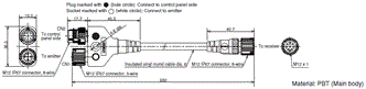
Interface Unit (F39-GIF, sold separately)
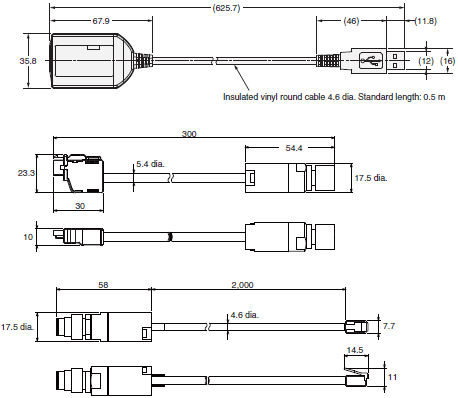
Spatter Protection Cover (F39-HGA, sold separately)
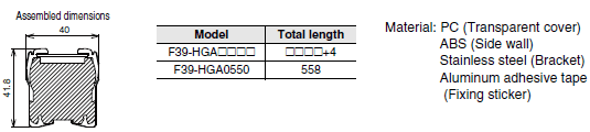
Bluetooth Communication Unit (F39-BT, sold separately)
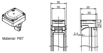
Lamp and Bluetooth Communication Unit(F39-BTLP, sold separately)
Lamp (F39-LP, sold separately)
F3SG-RR Robust type
Mounted with Free-Location Brackets (F39-LGRA)
Backside Mounting
Side Mounting
Mounted with Top/Bottom Brackets (F39-LGRTB) and Intermediate Bracket (F39-LGRA)
Backside Mounting
Side Mounting
Mounted with Top/Bottom Brackets (F39-LGRTB-2) and Intermediate Bracket (F39-LGRA)
Backside Mounting
Side Mounting
Mounted with Top/Bottom Brackets (F39-LGRTB-3) and Intermediate Bracket (F39-LGRA)
Backside Mounting
Side Mounting
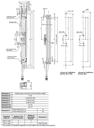
Accessories
Sensor Mounting Brackets
Free-Location Bracket / Intermediate Bracket (F39-LGRA, sold separately)
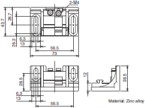
Top/Bottom Bracket (F39-LGRTB, sold separately)
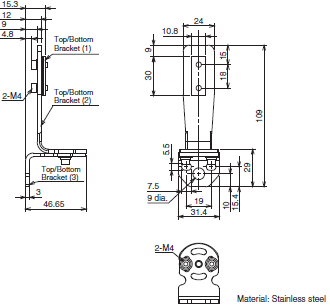
Top/Bottom Bracket (F39-LGRTB-2, sold separately)
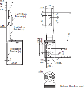
Top/Bottom Bracket (F39-LGRTB-3, sold separately)
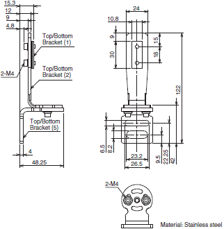
Safety light curtain connecting cable
Single-Ended Cable for Emitter (Oil-Resistant Cable) (F39-JD[]RA-L, sold separately)
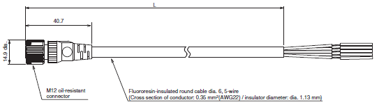
Single-Ended Cable for Receiver (Oil-Resistant Cable) (F39-JD[]RA-D, sold separately)
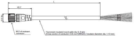
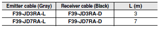
Single-Ended Cable for Emitter (F39-JD[]A-L, sold separately)
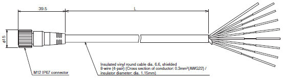
Single-Ended Cable for Receiver (F39-JD[]A-D, sold separately)
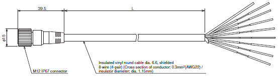
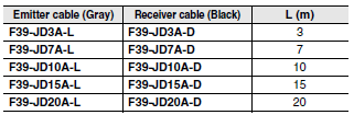
Double-Ended Cable for Emitter: Cable for extension (F39-JD[]B-L, sold separately)
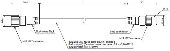
Double-Ended Cable for Receiver: Cable for extension (F39-JD[]B-D, sold separately)
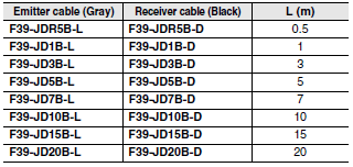
Reduced Wiring Connector (F39-CN5, sold separately)
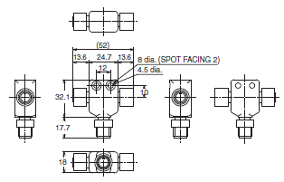
Cascading Cable for Emitter (F39-JGR2WTS-L, sold separately)
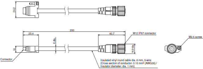
Cascading Cable for Receiver (F39-JGR2WTS-D, sold separately)
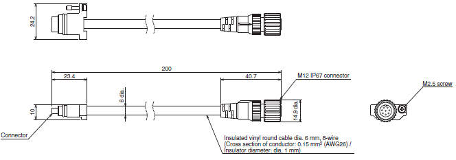

Interface Unit (F39-GIF-1, sold separately)
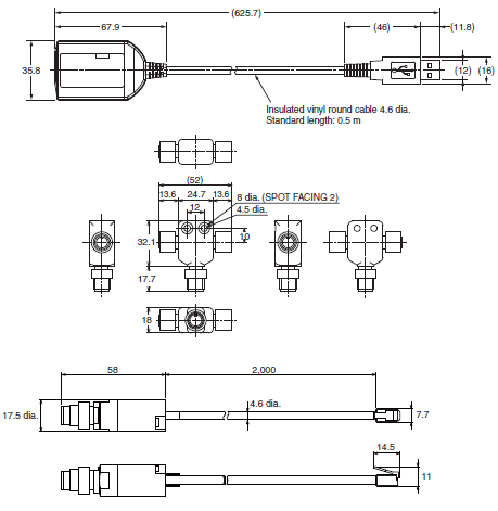
Bluetooth Communication Unit (F39-BT, sold separately)
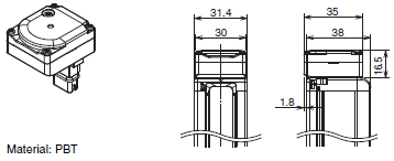
Lamp and Bluetooth Communication Unit (F39-BTLP, sold separately) Lamp (F39-LP, sold separately)
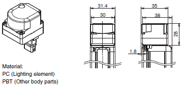
F3SG-RE Easy type
Mounted with Standard Fixed Brackets (F39-LGF)
Backside Mounting
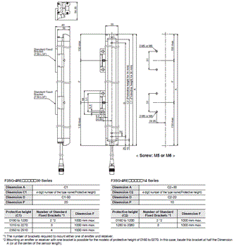
Side Mounting
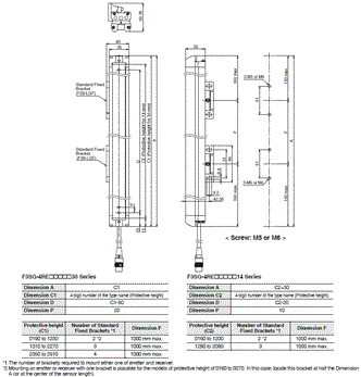
Mounted with Standard Fixed Brackets (F39-LGA)
Backside Mounting
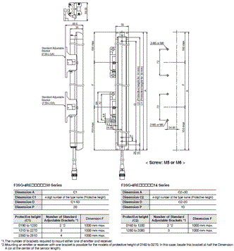
Side Mounting
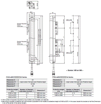
Mounted with Top/Bottom Adjustable Brackets (F39-LGTB) and Standard Adjustable Brackets (F39-LGA)
Dimensions when using the F3SG-RE Series except the F3SG-4RE0190[]30 and F3SG-4RE0160[]14
Refer to Safety Light Curtain F3SG-R Series User's Manual for the dimensions when using the F3SG-4RE0190[]30 and F3SG-4RE0160[]14.
Backside Mounting
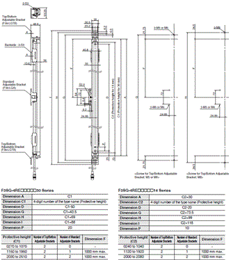
Side Mounting
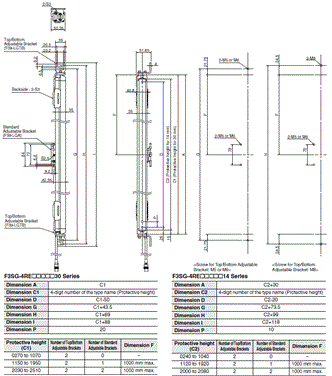
Accessories
Sensor Mounting Brackets
Standard Fixed Bracket (F39-LGF)
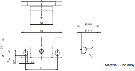
Standard Fixed Bracket (F39-LGA, sold separately)
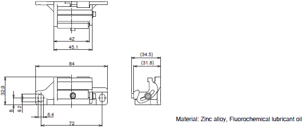
Top/Bottom Adjustable Bracket (F39-LGTB, sold separately)
Safety light curtain connecting cable
Round Water-resistant Connector: Connector Connected to Cable, Socket on One Cable End (XS5F-D421-[]80-F, sold separately)
Round Water-resistant Connector: Connectors Connected to Cable, Socket and Plug on Cable Ends (XS5W-D421-[]81-F, sold separately)
Y-Joint Plug/Socket Connector (F39-GCNY1, sold separately)
Spatter Protection Cover(F39-HGA/-HGB, sold separately)
F3SG-RA-01TS
Mounted with Standard Fixed Brackets (F39-LGF)
Backside Mounting
Side Mounting
>
Mounted with Standard Adjustable Brackets (F39-LGA)
Backside Mounting
Side Mounting
Mounted with Top/Bottom Adjustable Brackets (F39-LGTB) and Standard Adjustable Brackets (F39-LGA)
Dimensions when using the F3SG-RA Series except the F3SG-4RA0185-25-01TS.
Refer to Safety Light Curtain F3SG-4RA[][][][]-25-01TS Series User's Manual for the dimensions when using the F3SG-4RA0185-25-01TS.
Backside Mounting
Side Mounting
Accessories
Sensor Mounting Brackets
Standard Fixed Bracket (F39-LGF, sold separately)
Standard Adjustable Bracket (F39-LGA, sold separately)
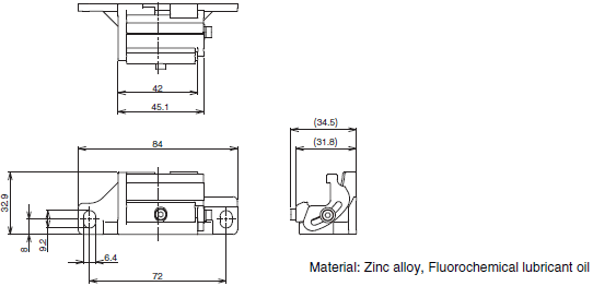
Top/Bottom Adjustable Bracket (F39-LGTB, sold separately)
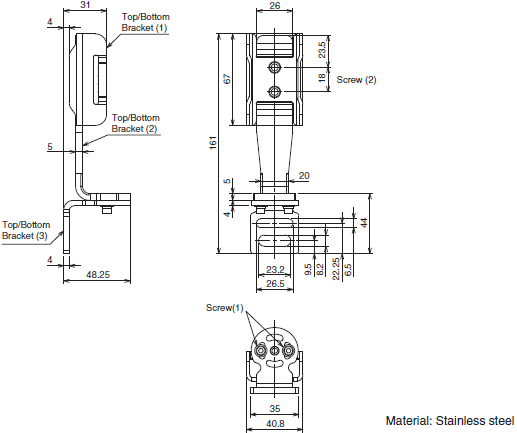
Safety light curtain connecting cable
Single-Ended Cable for Emitter (F39-JD[]A-L, sold separately)
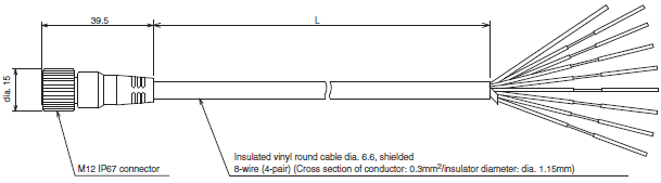
Single-Ended Cable for Receiver (F39-JD[]A-D, sold separately)
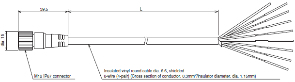
Double-Ended Cable for Emitter: Cable for extension (F39-JD[]B-L, sold separately)
Double-Ended Cable for Receiver: Cable for extension (F39-JD[]B-D, sold separately)
Reduced Wiring Connector (F39-CN5, sold separately)
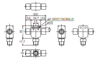
Cascading Cable for Emitter (F39-JGR2WTS-L, sold separately)
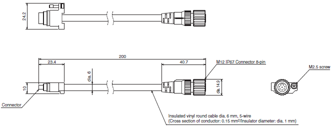
Cascading Cable for Receiver (F39-JGR2WTS-D, sold separately)
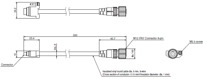

Interface Unit (F39-GIF, sold separately)
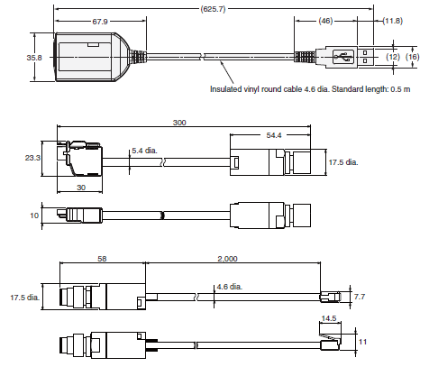
Spatter Protection Cover (F39-HGA, sold separately)
Bluetooth Communication Unit (F39-BT, sold separately)
Lamp and Bluetooth Communication Unit (F39-BTLP, sold separately)
Lamp (F39-LP, sold separately)
F3SG-RA-02TS
Mounted with Free-Location Brackets (F39-LGRA)
Backside Mounting
Side Mounting
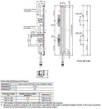
Mounted with Top/Bottom Brackets (F39-LGRTB) and Intermediate Bracket (F39-LGRA)
Backside Mounting
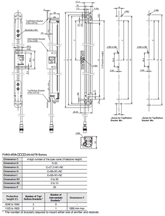
Side Mounting
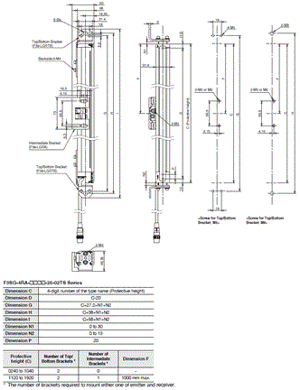
Mounted with Top/Bottom Brackets (F39-LGRTB-2) and Intermediate Bracket (F39-LGRA)
Backside Mounting
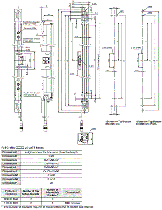
Side Mounting
Mounted with Top/Bottom Brackets (F39-LGRTB-3) and Intermediate Bracket (F39-LGRA)
Backside Mounting
Side Mounting
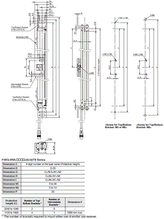
Accessories
Sensor Mounting Brackets
Free-Location Bracket / Intermediate Bracket (F39-LGRA, sold separately
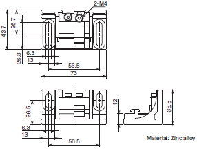
Top/Bottom Bracket (F39-LGRTB, sold separately)
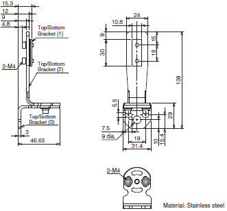
Top/Bottom Bracket (F39-LGRTB-2, sold separately)
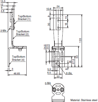
Top/Bottom Bracket (F39-LGRTB-3, sold separately)
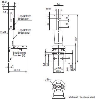
Safety light curtain connecting cable
Single-Ended Cable for Emitter (Oil-Resistant Cable) (F39-JD[]RA-L, sold separately)
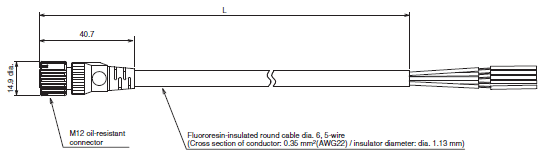
Single-Ended Cable for Receiver (Oil-Resistant Cable) (F39-JD[]RA-D, sold separately)
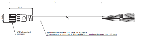
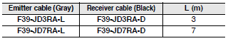
Single-Ended Cable for Emitter (F39-JD[]A-L, sold separately)
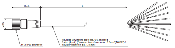
Single-Ended Cable for Receiver (F39-JD[]A-D, sold separately)
Double-Ended Cable for Emitter: Cable for extension (F39-JD[]B-L, sold separately)
Double-Ended Cable for Receiver: Cable for extension (F39-JD[]B-D, sold separately)

Reduced Wiring Connector (F39-CN5, sold separately)
Cascading Cable for Emitter (F39-JGR2WTS-L, sold separately)
Cascading Cable for Receiver (F39-JGR2WTS-D, sold separately)

Interface Unit (F39-GIF-1, sold separately)
Bluetooth Communication Unit (F39-BT, sold separately)
Lamp and Bluetooth Communication Unit (F39-BTLP, sold separately)
Lamp (F39-LP, sold separately)
Features | Safety Light Curtain - F3SG-R series
- System installed and highly susceptible to changing conditions
- Quick mount brackets reduce setup time by 50%
- Optical synchronization - No sync lines required
- Simple wiring thanks to reduced wiring connectors
- Scan QR code with smart phone for local language support and troubleshooting guide
- All models designed for global use. PNP/NPN outputselection by DIP switch
- Fast response time of 8ms
- ADVANCE model supports complex safety solutions with muting and blanking functions. F3SG-RE[Reduced wiring and fast response] Simple ON/OFF detection
- Easy version for cost-efficiency
- Fast response time of 5 ms
- QR code indication for easy online troubleshooting
- For stand-alone devices.
Properties | Safety Light Curtain - F3SG-R series
| Safety Light Curtain | F3SG-RA | F3SG-RE | F3SG-RR |
|---|---|---|---|
| Object Resolution | Ø 14 / 30 mm | Ø 14 / 30 mm | Ø 14 / 25 mm |
| Beam gap | 10 / 20 mm | 10 / 30 mm | 10 / 20 mm |
| Number of beams | 15-207 / 8-124 | 15-207 / 8-124 | 23-191 / 12-96 |
| Height | 160-2080 / 190-2510 mm | 160-2080 / 190-2510 mm | 240-1920 mm |
| Dimensions | 5.2 x 3.4 mm / 7mm dia. | 5.2 x 3.4 mm / 7mm dia. | 5.2 x 3.4 mm / 6.0 x 5.0 mm |
| Enclosure | 65 / 67 | 65 / 67 | 67 / 67G |
| Rangevoltage | 24 VDC | ||
| Safety Output | 2Port(PNPorNPN) , 24 VDC Current300 mA | ||
| Auxiliary Output | 1 Port(PNPorNPN), 24 VDCCurrent 100 mA | ||
Safety Light Curtain - F3SG-R series
ดาวน์โหลดไฟล์ PDF คุณสมบัติ | Safety Light Curtain - F3SG-R series
ม่านแสงนิรภัย มีทั้งความทนทาน และความน่าเชื่อถือ
- F3SG-RA
- ติดตั้งรวดเร็ว และมีความทนทานต่อการเปลี่ยนแปลงทางสภาพแวดล้อมสูง
- ขายึดปรับแนวเพื่อปรับลำแสงให้ง่ายขึ้น ลดเวลาในการติดตั้งลง 50%
- ลดความจำเป็นในการเดินสายสำหรับซิงโครไนซ์ระหว่างตัวรับและตัวส่ง แบบออปติคัล
- ประหยัดพื้นที่ในการติดตั้ง และเดินสายไฟง่าย (1 เส้น) ช่วยลดความเสี่ยงในการขาดความเชื่อมต่อ
- QR Code เพื่อแก้ปัญหาออนไลน์
- ออกแบบเพื่อใช้งานทั่วโลก การเลือกเอาต์พุตแบบ PNP/NPN โดย DIP Switch
- เวลาตอบสนองที่รวดเร็ว 8 ms
- รุ่น Advance รองรับวิธีการด้านความปลอดภัยที่ซับซ้อน
- F3SG-RE
- ลดสายไฟลง และการตอบสนองที่รวดเร็ว
- Easy version สำหรับค่าใช้จ่าย และประสิทธิภาพ
- เวลาตอบสนองที่รวดเร็ว 5 ms
- QR Code เพื่อแก้ปัญหาออนไลน์
- สำหรับอุปกรณ์ stand-alone
- F3SG-RR
- ออกแบบให้แข็งแรงเพื่อความน่าเชื่อถือ และใช้งานในสภาพแวดล้อมที่มีน้ำมัน (IP 67G)
- ทนทานต่อน้ำมัน
- QR Code เพื่อแก้ปัญหาออนไลน์
ข้อมูลจำเพาะ | Safety Light Curtain - F3SG-R series
| Safety Light Curtain | F3SG-RA | F3SG-RE | F3SG-RR |
|---|---|---|---|
| ความสามารถในการตรวจจับวัตถุ | Ø 14 / 30 mm | Ø 14 / 30 mm | Ø 14 / 25 mm |
| ระยะห่างของลำแสง | 10 / 20 mm | 10 / 30 mm | 10 / 20 mm |
| จำนวนของลำแสง | 15-207 / 8-124 | 15-207 / 8-124 | 23-191 / 12-96 |
| ความสูง | 160-2080 / 190-2510 mm | 160-2080 / 190-2510 mm | 240-1920 mm |
| ขนาด (W x H) | 5.2 x 3.4 mm / 7mm dia. | 5.2 x 3.4 mm / 7mm dia. | 5.2 x 3.4 mm / 6.0 x 5.0 mm |
| IP | 65 / 67 | 65 / 67 | 67 / 67G |
| แรงดัน | 24 VDC | ||
| Safety Output | 2 ช่องเลือกได้ระหว่าง PNP กับ NPN, แรงดัน 24 VDC กระแส 300 mA | ||
| เอาต์พุตเสริม | 1 ช่องเลือกได้ระหว่าง PNP กับ NPN, แรงดัน 24 VDC กระแส 100 mA | ||


 Your Lift