
OMRON Fiber Sensor - E32 series
Fiber Sensors, Fiber Units - E32 Series
Metal Head for long-distance Detection that Withstands Harsh Environments Where the Workpiece Can Rub against the Sensor
Download PDF
Model Numbers | Fiber Sensors, Fiber Units - E32 Series
Standard Installation
Threaded Models
Through-beam Fiber Units
| Sensing direction (Aperture angle) | Size | Appearance (mm) | Bending radius of cable | Sensing distance (mm) | Optical axis diameter (minimum sensing object) | Models | |
|---|---|---|---|---|---|---|---|
| E3X-HD | E3NX-FA | ||||||
| Rightangle (Approx. 60°) | M4 |  IP67 IP67 |
Flexible, R1 | GIGA: 2,000 HS: 700 ST: 1,000 SHS: 280 |
GIGA: 3,000 HS: 1,050 ST: 1,500 SHS: 280 |
1 dia. (5 μm dia./ 2 μm dia.) |
E32-T11N 2M |
| Top-view (Approx. 60°) |
 IP67 IP67 |
E32-T11R 2M | |||||
| Top-view (Approx. 15°) |
 IP50 IP50 |
R25 | GIGA: 4,000 * HS: 2,700 ST: 4,000 * SHS: 1,080 |
GIGA: 4,000 * HS: 4,000 * ST: 4,000 * SHS: 1,080 |
2.3 dia. (0.1 dia./ 0.03 dia.) |
E32-LT11 2M | |
| Flexible, R1 |
GIGA: 2,000 HS: 2,300 ST: 3,500 SHS: 920 |
GIGA: 4,000 * HS: 3,450 ST: 4,000 * SHS: 920 |
E32-LT11R 2M | ||||
Note 1. The following mode names and response times apply to the modes given in the Sensing distance column.
[E3X-HD] GIGA: Giga-power mode (16 ms), HS: High-speed mode (250 μs), ST: Standard mode (1 ms), and
SHS: Super-high-speed mode (NPN output: 50 μs, PNP output: 55 μs)
[E3NX-FA] GIGA: Giga-power mode (16 ms), HS: High-speed mode (250 μs), ST: Standard mode (1 ms), and
SHS: Super-high-speed mode (30 μs)
2. The values for the minimum sensing object are reference values that indicate values obtained in standard mode
with the sensing distance and sensitivity set to the optimum values.
The first value is for the E3X-HD and the second value is for the E3NX-FA.
3. The sensing distances for E3NX-FA are values for E3NX-FA[] models. The distances for E3NX-FAH[] infrared models are different.
Reflective Fiber Units
| Sensing direction (Aperture angle) | Size | Appearance (mm) | Bending radius of cable | Sensing distance (mm) | Optical axis diameter (minimum sensing object) | Models | |
|---|---|---|---|---|---|---|---|
| E3X-HD | E3NX-FA | ||||||
| Right-angle (Approx. 60°) | M3 | Coaxial  IP67 |
Flexible, R4 |
GIGA: 110 HS: 46 ST: 50 SHS: 14 |
GIGA: 160 HS: 69 ST: 75 SHS: 14 |
(5 μm dia./ 2 μm dia.) |
E32-C31N 2M |
| M6 | Coaxial  IP67 |
GIGA: 780 HS: 220 ST: 350 SHS: 100 |
GIGA: 1,170 HS: 340 ST: 520 SHS: 100 |
E32-C91N 2M | |||
| Top-view (Approx. 60°) | M3 |  IP67 |
Flexible, R1 |
GIGA: 140 HS: 40 ST: 60 SHS: 16 |
GIGA: 210 HS: 60 ST: 90 SHS: 16 |
E32-D21R 2M | |
Coaxial  IP67 |
R25 | GIGA: 330 HS: 100 ST: 150 SHS: 44 |
GIGA: 490 HS: 150 ST: 220 SHS: 44 |
E32-C31 2M | |||
Coaxial  IP67 |
R10 | E32-C31M 1M | |||||
| M4 |  IP67 |
Flexible, R1 |
GIGA: 140 HS: 40 ST: 60 SHS: 16 |
GIGA: 210 HS: 60 ST: 90 SHS: 16 |
E32-D211R 2M | ||
| M6 |  IP67 |
GIGA: 840 HS: 240 ST: 350 SHS: 100 |
GIGA: 1,260 HS: 360 ST: 520 SHS: 100 |
E32-D11R 2M | |||
Coaxial  IP67 |
R25 | GIGA: 1,400 HS: 400 ST: 600 SHS: 180 |
GIGA: 2,100 HS: 600 ST: 900 SHS: 180 |
E32-CC200 2M | |||
| Top-view (Approx. 15°) | M6 |  IP50 |
R25 | GIGA: 860 HS: 250 ST: 360 SHS: 110 |
GIGA: 1,290 HS: 370 ST: 540 SHS: 110 |
(1 dia./ 0.03 dia.) |
E32-LD11 2M |
| Flexible, R1 |
GIGA: 840 HS: 240 ST: 350 SHS: 100 |
GIGA: 1,260 HS: 360 ST: 520 SHS: 100 |
E32-LD11R 2M | ||||
[E3X-HD] GIGA: Giga-power mode (16 ms), HS: High-speed mode (250 μs), ST: Standard mode (1 ms), and
SHS: Super-high-speed mode (NPN output: 50 μs, PNP output: 55 μs)
[E3NX-FA] GIGA: Giga-power mode (16 ms), HS: High-speed mode (250 μs), ST: Standard mode (1 ms), and
SHS: Super-high-speed mode (30 μs)
2. The values for the minimum sensing object are reference values that indicate values obtained in standard mode
with the sensing distance and sensitivity set to the optimum values.
The first value is for the E3X-HD and the second value is for the E3NX-FA.
3. The sensing distances for Reflective Fiber Units are for white paper. (The sensing distance for the E32-LD11 2M/
E32-LD11R 2M are for glossy white paper.)
4. The sensing distances for E3NX-FA are values for E3NX-FA[] models. The distances for E3NX-FAH[] infrared models
are different.
Cylindrical Models
Through-beam Fiber Units
| Size | Sensing direction | Appearance (mm) | Bending radius of cable | Sensing distance (mm) | Optical axis diameter (minimum sensing object) | Models | |
|---|---|---|---|---|---|---|---|
| E3X-HD | E3NX-FA | ||||||
| 1 dia. | Top-View |  IP67 IP67 |
Flexible, R1 |
GIGA: 450 HS: 150 ST: 250 SHS: 60 |
GIGA: 670 HS: 220 ST: 370 SHS: 60 |
0.5 dia. (5 μm dia./ 2 μm dia.) |
E32-T223R 2M |
| 1.5 dia. |
 IP67 IP67 |
Bend- resistant, R4 |
GIGA: 680 HS: 220 ST: 400 SHS: 90 |
GIGA: 1,020 HS: 330 ST: 600 SHS: 90 |
E32-T22B 2M | ||
| 3 dia. |
 IP67 IP67 |
Flexible, R1 |
GIGA: 2,000 HS: 700 ST: 1,000 SHS: 280 |
GIGA: 3,000 HS: 1,050 ST: 1,500 SHS: 280 |
1 dia. (5 μm dia./ 2 μm dia.) |
E32-T12R 2M | |
| Side-View |  IP67 IP67 |
GIGA: 750 HS: 260 ST: 450 SHS: 100 |
GIGA: 1,120 HS: 390 ST: 670 SHS: 100 |
E32-T14LR 2M | |||
1. The following mode names and response times apply to the modes given in the Sensing distance column. [E3X-HD] GIGA: Giga-power mode (16 ms), HS: High-speed mode (250 μs), ST: Standard mode (1 ms), and SHS: Super-high-speed mode (NPN output: 50 μs, PNP output: 55 μs) [E3NX-FA] GIGA: Giga-power mode (16 ms), HS: High-speed mode (250 μs), ST: Standard mode (1 ms), and SHS: Super-high-speed mode (30 μs)
2. The values for the minimum sensing object are reference values that indicate values obtained in standard mode with the sensing distance and sensitivity set to the optimum values. The first value is for the E3X-HD and the second value is for the E3NX-FA.
3. The sensing distances for E3NX-FA are values for E3NX-FA[] models. The distances for E3NX-FAH[] infrared models are different.
Reflective Fiber Units
| Size | Sensing direction | Appearance (mm) | Bending radius of cable | Sensing distance (mm) | Optical axis diameter (minimum sensing object) | Models | |
|---|---|---|---|---|---|---|---|
| E3X-HD | E3NX-FA | ||||||
| 1.5 dia. | Top-View |  IP67 IP67 |
Bend- resistant, R4 |
GIGA: 140 HS: 40 ST: 60 SHS: 16 |
GIGA: 210 HS: 60 ST: 90 SHS: 16 |
(5 μm dia./ 2 μm dia.) |
E32-D22B 2M |
| 1.5 dia. + 0.5 dia. |
The sleeve cannot be bent.  IP67 IP67 |
R4 | GIGA: 28 HS: 8 ST: 12 SHS: 4 |
GIGA: 42 HS: 12 ST: 18 SHS: 4 |
E32-D43M 1M | ||
| 3 dia. |  IP67 IP67 |
Flexible, R1 | GIGA: 140 HS: 40 ST: 60 SHS: 16 |
GIGA: 210 HS: 60 ST: 90 SHS: 16 |
E32-D22R 2M | ||
 IP67 IP67 |
Bend-resistant, R4 | GIGA: 300 HS: 90 ST: 140 SHS: 40 |
GIGA: 450 HS: 130 ST: 210 SHS: 40 |
E32-D221B 2M | |||
Coaxial  IP67 IP67 |
R25 | GIGA: 700 HS: 200 ST: 300 SHS: 90 |
GIGA: 1,050 HS: 300 ST: 450 SHS: 90 |
E32-D32L 2M | |||
| 3 dia. + 0.8 dia. |
The sleeve cannot be bent.  IP67 IP67 |
GIGA: 70 HS: 20 ST: 30 SHS: 8 |
GIGA: 100 HS: 30 ST: 45 SHS: 8 |
E32-D33 2M | |||
2. The values for the minimum sensing object are reference values that indicate values obtained in standard mode with the sensing distance and sensitivity set to the optimum values. The first value is for the E3X-HD and the second value is for the E3NX-FA.
3. The sensing distances for Reflective Fiber Units are for white paper.
4. The sensing distances for E3NX-FA are values for E3NX-FA[] models. The distances for E3NX-FAH[] infrared models are different.
Saving Space
Flat Models
Through-beam Fiber Units
| Sensing direction | Appearance (mm) | Bending radius of cable | Sensing distance (mm) | Optical axis diameter (minimum sensing object) | Models | |
|---|---|---|---|---|---|---|
| E3X-HD | E3NX-FA | |||||
| Top-View |  IP67 |
Flexible, R1 |
GIGA: 2,000 HS: 700 ST: 1,000 SHS: 280 |
GIGA: 3,000 HS: 1,050 ST: 1,500 SHS: 280 |
1 dia. (5 μm dia./ 2 μm dia.) |
E32-T15XR 2M |
| Side-View |  IP67 |
GIGA: 750 HS: 260 ST: 450 SHS: 100 |
GIGA: 1,120 HS: 390 ST: 670 SHS: 100 |
E32-T15YR 2M | ||
| Flat-View |  IP67 |
E32-T15ZR 2M | ||||
 IP40 |
GIGA: 2,400 HS: 800 ST: 1,200 SHS: 30 |
GIGA: 3,600 HS: 1,200 ST: 1,800 SHS: 300 |
3 dia. (0.1 dia./ 0.03 dia.) |
E32-LT35Z 2M | ||
Reflective Fiber Units
| Sensing direction | Appearance (mm) | Bending radius of cable | Sensing distance (mm) | Optical axis diameter (minimum sensing object) | Models | |
|---|---|---|---|---|---|---|
| E3X-HD | E3NX-FA | |||||
| Top-View |  IP67 IP67 |
Flexible, R1 |
GIGA: 840 HS: 240 ST: 350 SHS: 100 |
GIGA: 1,260 HS: 360 ST: 520 SHS: 100 |
(5 μm dia./ 2 μm dia.) |
E32-D15XR 2M |
| Side-View |  IP67 IP67 |
GIGA: 200 HS: 52 ST: 100 SHS: 24 |
GIGA: 300 HS: 78 ST: 150 SHS: 24 |
E32-D15YR 2M | ||
| Flat-View |  IP67 IP67 |
E32-D15ZR 2M | ||||
[E3NX-FA] GIGA: Giga-power mode (16 ms), HS: High-speed mode (250 μs), ST: Standard mode (1 ms), and SHS: Super-high-speed mode (30 μs)
2. The values for the minimum sensing object are reference values that indicate values obtained in standard mode with the sensing distance and sensitivity set to the optimum values. The first value is for the E3X-HD and the second value is for the E3NX-FA.
3. The sensing distances for Reflective Fiber Units are for white paper.
4. The sensing distances for E3NX-FA are values for E3NX-FA[] models. The distances for E3NX-FAH[] infrared models are different.
Sleeve Models (Close-range Detection)
Through-beam Fiber Units
| Sensing direction | Appearance (mm) | Bending radius of cable | Sensing distance (mm) | Optical axis diameter (minimum sensing object) | Models | |
|---|---|---|---|---|---|---|
| E3X-HD | E3NX-FA | |||||
| Side-View | The sleeve cannot be bent.  IP67 IP67 |
Flexible, R1 |
GIGA: 170 HS: 50 ST: 100 SHS: 20 |
GIGA: 250 HS: 75 ST: 150 SHS: 20 |
0.5 dia. (5 μm dia./ 2 μm dia.) |
E32-T24R 2M |
| The sleeve cannot be bent.  IP67 IP67 |
R10 | GIGA: 450 HS: 150 ST: 250 SHS: 60 |
GIGA: 670 HS: 220 ST: 370 SHS: 60 |
E32-T24E 2M | ||
| Top-View | The sleeve cannot be bent.  IP67 IP67 |
GIGA: 150 HS: 50 ST: 90 SHS: 20 |
GIGA: 220 HS: 75 ST: 130 SHS: 20 |
0.25 dia. (5 μm dia./ 2 μm dia.) |
E32-T33 1M | |
| The sleeve cannot be bent.  IP67 IP67 |
GIGA: 510 HS: 170 ST: 300 SHS: 68 |
GIGA: 760 HS: 250 ST: 450 SHS: 68 |
0.5 dia. (5 μm dia./ 2 μm dia.) |
E32-T21-S1 2M | ||
| Sleeve bending radius: 5 mm  IP67 IP67 |
Flexible, R1 |
GIGA: 2,000 HS: 700 ST: 1,000 SHS: 280 |
GIGA: 3,000 HS: 1,050 ST: 1,500 SHS: 280 |
1 dia. (5 μm dia./ 2 μm dia.) |
E32-TC200BR 2M | |
[E3X-HD] GIGA: Giga-power mode (16 ms), HS: High-speed mode (250 μs), ST: Standard mode (1 ms), and SHS: Super-high-speed mode (NPN output: 50 μs, PNP output: 55 μs) [E3NX-FA] GIGA: Giga-power mode (16 ms), HS: High-speed mode (250 μs), ST: Standard mode (1 ms), and SHS: Super-high-speed mode (30 μs)
2. The values for the minimum sensing object are reference values that indicate values obtained in standard mode with the sensing distance and sensitivity set to the optimum values.
The first value is for the E3X-HD and the second value is for the E3NX-FA.
3. The sensing distances for E3NX-FA are values for E3NX-FA[] models. The distances for E3NX-FAH[] infrared models are different.
Reflective Fiber Units
| Sensing direction | Appearance (mm) | Bending radius of cable | Sensing distance (mm) | Optical axis diameter (minimum sensing object) | Models | |
|---|---|---|---|---|---|---|
| E3X-HD | E3NX-FA | |||||
| Side-View | The sleeve cannot be bent  IP67 IP67 |
Flexible, R1 |
GIGA: 70 HS: 20 ST: 30 SHS: 8 |
GIGA: 100 HS: 30 ST: 45 SHS: 8 |
(5 μm dia./ 2 μm dia.) |
E32-D24R 2M |
| Sleeve bending radius: 25 mm  IP67 IP67 |
R25 | GIGA: 120 HS: 45 ST: 53 SHS: 14 |
GIGA: 180 HS: 67 ST: 79 SHS: 14 |
E32-D24-S2 2M | ||
| Top-View | The sleeve cannot be bent.  IP67 IP67 |
R4 | GIGA: 28 HS: 8 ST: 12 SHS: 4 |
GIGA: 42 HS: 12 ST: 18 SHS: 4 |
E32-D43M 1M | |
| The sleeve cannot be bent.  IP67 IP67 |
GIGA: 14 HS: 4 ST: 6 SHS: 2 |
GIGA: 21 HS: 6 ST: 9 SHS: 2 |
E32-D331 2M | |||
| The sleeve cannot be bent.  IP67 IP67 |
R25 | GIGA: 70 HS: 20 ST: 30 SHS: 8 |
GIGA: 100 HS: 30 ST: 45 SHS: 8 |
E32-D33 2M | ||
| The sleeve cannot be bent.  IP67 IP67 |
R4 | GIGA: 63 HS: 18 ST: 27 SHS: 7 |
GIGA: 94 HS: 27 ST: 40 SHS: 7 |
E32-D32-S1 0.5M | ||
| The sleeve cannot be bent.  IP67 IP67 |
E32-D31-S1 0.5M | |||||
| Sleeve bending radius: 5 mm  IP67 IP67 |
Flexible, R1 |
GIGA: 140 HS: 40 ST: 60 SHS: 16 |
GIGA: 210 HS: 60 ST: 90 SHS: 16 |
E32-DC200F4R 2M | ||
| The sleeve cannot be bent.  IP67 IP67 |
R10 | GIGA: 250 HS: 72 ST: 110 SHS: 30 |
GIGA: 370 HS: 100 ST: 160 SHS: 30 |
E32-D22-S1 2M | ||
| Sleeve bending radius: 10 mm  IP67 IP67 |
E32-D21-S3 2M | |||||
| The sleeve cannot be bent.  IP67 IP67 |
Flexible, R1 |
GIGA: 840 HS: 240 ST: 350 SHS: 100 |
GIGA: 1,260 HS: 360 ST: 520 SHS: 100 |
E32-DC200BR 2M | ||
| Sleeve bending radius: 10 mm  IP67 IP67 |
R10 | GIGA: 250 HS: 72 ST: 110 SHS: 30 |
GIGA: 370 HS: 100 ST: 160 SHS: 30 |
E32-D25-S3 2M | ||
2. The values for the minimum sensing object are reference values that indicate values obtained in standard mode with the sensing distance and sensitivity set to the optimum values. The first value is for the E3X-HD and the second value is for the E3NX-FA.
3. The sensing distances for Reflective Fiber Units are for white paper.
4. The sensing distances for E3NX-FA are values for E3NX-FA[] models. The distances for E3NX-FAH[] infrared models are different.
Beam Improvements
Small-Spot, Reflective (Minute Object Detection)
Reflective Fiber Units
Variable-spot types
Lens Units + Fiber Unit
| Type | Spot diameter | Center distance (mm) | Lens Units | Lens Units + Fiber Units | Fiber Unit | |
|---|---|---|---|---|---|---|
| Models | Appearance (mm) | Bending radius of cable | Model | |||
| Variable spot | 0.1 to 0.6 dia. | 6 to 15 | E39-F3A |  |
R25 | E32-C42 1M |
| 0.3 to 1.6 dia. | 10 to 30 | E39-F17 |  |
|||
Parallel-light-spot types
Lens Unit + Fiber Units
| Type | Spot diameter | Center distance (mm) | Lens Units | Lens Units + Fiber Units | Fiber Unit | |
|---|---|---|---|---|---|---|
| Models | Appearance (mm) | Bending radius of cable | Model | |||
| Parallel light | 4 dia. | 0 to 20 | E39-F3C |  |
R25 | E32-C31 2M |
 |
Flexible, R2 | E32-C21N 2M | ||||
Small-spot types
Integrated Lens
| Type | Spot diameter | Center distance (mm) | Appearance (mm) | Bending radius of cable | Models |
|---|---|---|---|---|---|
| Short-distance, Small-spot | 0.1 dia. | 5 |  Lens: unnecessary Lens: unnecessary IP50 |
R25 | E32-C42S 1M |
| Long-distance, Small-spot | 6 dia. | 50 |  Lens: unnecessary Lens: unnecessary IP50 |
E32-L15 2M |
Small-spot Models
Lens Units + Fiber Units
| Type | Spot diameter | Center distance (mm) | Lens Units | Lens Units + Fiber Units | Fiber Unit | |
|---|---|---|---|---|---|---|
| Models | Appearance (mm) | Bending radius of cable | Models | |||
| Short-distance, small-spot | 0.1 dia. | 7 | E39-F3A-5 |  |
R25 | E32-C41 1M |
| 0.5 dia. |  |
E32-C31 2M | ||||
 |
Flexible, R2 | E32-C21N 2M | ||||
| Medium-distance, small-spot | 0.2 dia. | 17 | E39-F3B |  |
R25 | E32-C41 1M |
| 0.5 dia. |  |
E32-C31 2M | ||||
 |
Flexible, R2 | E32-C21N 2M | ||||
| Long-distance, small-spot | 3 dia. | 50 | E39-F18 |  |
R25 | E32-CC200 2M |
 |
Flexible, R4 | E32-C91N 2M | ||||
High-power Beam (Long-distance Installation, Dust-resistant)
Fiber only
Through-beam Fiber Units
| Sensing direction | Aperture angle | Appearance (mm) | Bending radius of cable | Sensing distance (mm) | Optical axis diameter (minimum sensing object) | Models | |
|---|---|---|---|---|---|---|---|
| E3X-HD | E3NX-FA | ||||||
| Right- angle | 15° |  IP50 |
Flexible, R2 | GIGA: 4,000 *1 HS: 2,300 ST: 3,500 SHS: 920 |
GIGA: 4,000 *1 HS: 3,450 ST: 4,000 *1 SHS: 920 |
2.3 dia. (0.1 dia./ 0.03 dia.) |
E32-LT11N 2M |
| Top- View | 10° |  IP67 |
R25 | GIGA: 20,000 *2 HS: 20,000 *2 ST: 20,000 *2 SHS: 8,000 |
GIGA: 20,000 *2 HS: 20,000 *2 ST: 20,000 *2 SHS: 8,000 |
10 dia. | E32-T17L 10M |
| 15° |  IP50 |
GIGA: 4,000 *1 HS: 2,700 ST: 4,000 *1 SHS: 1,080 |
GIGA: 4,000 *1 HS: 4,000 *1 ST: 4,000 *1 SHS: 1,080 |
2.3 dia. (0.1 dia./ 0.03 dia.) |
E32-LT11 2M | ||
| Flexible, R1 | GIGA: 4,000 *1 HS: 2,300 ST: 3,500 SHS: 920 |
GIGA: 4,000 *1 HS: 3,450 ST: 4,000 *1 SHS: 920 |
E32-LT11R 2M | ||||
| Side- View | 30° |  IP67 |
R25 | GIGA: 4,000 *1 HS: 4,000 *1 ST: 4,000 *1 SHS: 1,800 |
GIGA: 4,000 *1 HS: 4,000 *1 ST: 4,000 *1 SHS: 1,800 |
4 dia. (0.1 dia./ 0.03 dia.) |
E32-T14 2M |
*2. The optical fiber is 2 m long on each side, so the sensing distance is 4,000 mm.
Note. The sensing distances for the E3NX-FA are values for E3NX-FA[] devices. The distance for E3NX-FAH[] infrared modelsvaries.
Reflective Fiber Units
| Sensing direction | Aperture angle | Appearance (mm) | Bending radius of cable | Sensing distance (mm) | Optical axis diameter (minimum sensing object) | Models | |
|---|---|---|---|---|---|---|---|
| E3X-HD | E3NX-FA | ||||||
| Top-View | 4° |  IP40 IP40 |
Bend-resistant, R4 | GIGA: 40 to 2,800 HS: 40 to 900 ST: 40 to 1,400 SHS: 40 to 480 |
GIGA: 40 to 4,000 *2 HS: 40 to 1,350 ST: 40 to 2,100 SHS: 40 to 480 |
- | E32-D16 2M |
1. The following mode names and response times apply to the modes given in the Sensing distance column. [E3X-HD] GIGA: Giga-power mode (16 ms), HS: High-speed mode (250 μs), ST: Standard mode (1 ms), and SHS: Super-high-speed mode (NPN output: 50 μs, PNP output: 55 μs) [E3NX-FA] GIGA: Giga-power mode (16 ms), HS: High-speed mode (250 μs), ST: Standard mode (1 ms), and SHS: Super-high-speed mode (30 μs)
2. The values for the minimum sensing object are reference values that indicate values obtained in standard mode with the sensing distance and sensitivity set to the optimum values. The first value is for the E3X-HD and the second value is for the E3NX-FA.
3. The sensing distances for Reflective Fiber Units are for white paper.
4. The sensing distances for the E3NX-FA are values for E3NX-FA[] devices. The distance for E3NX-FAH[] infrared models varies.
Lens (to 70°C)
Through-beam Fiber Units
| Lens Units | Type | High-power (incident level: 50 times) | Ultra-high-power (incident level: 160 times) | Side-View (incident level: 0.8 times) | |||
|---|---|---|---|---|---|---|---|
| Models | E39-F1 | E39-F16 | E39-F2 | ||||
| Appearance |  |  |  | ||||
| Aperture angle | Approx. 12° | Approx. 6° | Approx. 60° | ||||
| Fiber Units | Optical axis diameter (minimum sensing object) | 4 dia. (0.1 dia.) | 7.2 dia. | 3 dia. (0.1 dia.) | |||
| Models | Appearance (mm) | Sensing distance (mm) | |||||
| E3X-HD | E3NX-FA | E3X-HD | E3NX-FA | E3X-HD | E3NX-FA | ||
| E32-T11N 2M |  |
GIGA: 4,000 * HS: 4,000 * ST: 4,000 * SHS: 2,000 |
GIGA: 4,000 * HS: 4,000 * ST: 4,000 * SHS: 2,000 |
GIGA: 4,000 * HS: 4,000 * ST: 4,000 * SHS: 3,600 |
GIGA: 4,000 * HS: 4,000 * ST: 4,000 * SHS: 3,600 |
- | - |
| E32-T11R 2M |  |
GIGA: 4,000 * HS: 4,000 * ST: 4,000 * SHS: 2,000 |
GIGA: 4,000 * HS: 4,000 * ST: 4,000 * SHS: 2,000 |
GIGA: 4,000 * HS: 4,000 * ST: 4,000 * SHS: 3,600 |
GIGA: 4,000 * HS: 4,000 * ST: 4,000 * SHS: 3,600 |
GIGA: 1,450 HS: 500 ST: 800 SHS: 200 |
GIGA: 2,170 HS: 750 ST: 1,200 SHS: 200 |
| E32-T11 2M |  |
GIGA: 4,000 * HS: 4,000 * ST: 4,000 * SHS: 1,860 |
GIGA: 4,000 * HS: 4,000 * ST: 4,000 * SHS: 1,860 |
GIGA: 4,000 * HS: 4,000 * ST: 4,000 * SHS: 4,000 * |
GIGA: 4,000 * HS: 4,000 * ST: 4,000 * SHS: 4,000 * |
GIGA: 2,300 HS: 860 ST: 1,320 SHS: 320 |
GIGA: 3,450 HS: 1,290 ST: 1,980 SHS: 320 |
Note
1. The following mode names and response times apply to the modes given in the Sensing distance column. [E3X-HD] GIGA: Giga-power mode (16 ms), HS: High-speed mode (250 μs), ST: Standard mode (1 ms), and SHS: Super-high-speed mode (NPN output: 50 μs, PNP output: 55 μs) [E3NX-FA] GIGA: Giga-power mode (16 ms), HS: High-speed mode (250 μs), ST: Standard mode (1 ms), and SHS: Super-high-speed mode (30 μs)
2. The values for the minimum sensing object are reference values that indicate values obtained in standard mode with the sensing distance and sensitivity set to the optimum values. The first value is for the E3X-HD and the second value is for the E3NX-FA.
3. The sensing distances for the E3NX-FA are values for E3NX-FA[] devices. The distance for E3NX-FAH[] infrared models varies.
Through-beam Fiber Units (Heat-resistant)
| Lens Units | Type | High-power (incident level: 50 times) | Ultra-high-power (incident level: 160 times) | Side-View (incident level: 0.8 times) | |||
|---|---|---|---|---|---|---|---|
| Models | E39-F1 | E39-F16 | E39-F2 | ||||
| Appearance |  |  |  | ||||
| Aperture angle | Approx. 12° | Approx. 6° | Approx. 60° | ||||
| Fiber Units | Optical axis diameter (minimum sensing object) | 4 dia. (0.1 dia.) | 7.2 dia. | 3 dia. (0.1 dia.) | |||
| Models | Appearance (mm) | Sensing distance (mm) | |||||
| E3X-HD | E3NX-FA | E3X-HD | E3NX-FA | E3X-HD | E3NX-FA | ||
| E32-T51R 2M | Heat-resistant up to 100°C  |
GIGA: 4,000 * HS: 3,900 ST: 4,000 * SHS: 1,500 |
GIGA: 4,000 * HS: 4,000 * ST: 4,000 * SHS: 1,500 |
GIGA: 4,000 * HS: 4,000 * ST: 4,000 * SHS: 4,000 * |
GIGA: 4,000 * HS: 4,000 * ST: 4,000 * SHS: 4,000 * |
GIGA: 1,400 HS: 500 ST: 720 SHS: 200 |
GIGA: 2,100 HS: 750 ST: 1,080 SHS: 200 |
| E32-T81R-S 2M | Heat-resistant up to 200°C  |
GIGA: 4,000 * HS: 2,700 ST: 4,000 * SHS: 1,000 |
GIGA: 4,000 * HS: 4,000 * ST: 4,000 * SHS: 1,000 |
GIGA: 4,000 * HS: 4,000 * ST: 4,000 * SHS: 1,800 |
GIGA: 4,000 * HS: 4,000 * ST: 4,000 * SHS: 1,800 |
GIGA: 1,000 HS: 360 ST: 550 SHS: 140 |
GIGA: 1,500 HS: 540 ST: 820 SHS: 140 |
| E32-T61-S 2M | Heat-resistant up to 350°C (200°C) (See Note 3)  |
GIGA: 4,000 * HS: 4,000 * ST: 4,000 * SHS: 1,800 |
GIGA: 4,000 * HS: 4,000 * ST: 4,000 * SHS: 1,800 |
GIGA: 4,000 * HS: 4,000 * ST: 4,000 * SHS: 3,100 |
GIGA: 4,000 * HS: 4,000 * ST: 4,000 * SHS: 3,100 |
GIGA: 1,680 HS: 600 ST: 900 SHS: 240 |
GIGA: 2,520 HS: 900 ST: 1,350 SHS: 240 |
Note
1. The following mode names and response times apply to the modes given in the Sensing distance column. [E3X-HD] GIGA: Giga-power mode (16 ms), HS: High-speed mode (250 μs), ST: Standard mode (1 ms), and SHS: Super-high-speed mode (NPN output: 50 μs, PNP output: 55 μs) [E3NX-FA] GIGA: Giga-power mode (16 ms), HS: High-speed mode (250 μs), ST: Standard mode (1 ms), and SHS: Super-high-speed mode (30 μs)
2. The values for the minimum sensing object are reference values that indicate values obtained in standard mode with the sensing distance and sensitivity set to the optimum values. The first value is for the E3X-HD and the second value is for the E3NX-FA.
3. The ambient temperature of E32-T61-S must be between −40 to 200°C when using it with E39-F1 or E39-F2 Lens Unit. The ambient temperature of E32-T61-S must be between −40 to 350°C when using it with E39-F16 Lens Unit.
4. The sensing distances for the E3NX-FA are values for E3NX-FA[] devices. The distance for E3NX-FAH[] infrared models varies.
| Lens Units | Type | High-power (incident level: 50 times) | Ultra-high-power (incident level: 160 times) | ||
|---|---|---|---|---|---|
| Models | E39-F1-33 | E39-F16 | |||
| Appearance |  |  | |||
| Aperture angle | Approx. 12° | Approx. 6° | |||
| Fiber Units | Optical axis diameter (minimum sensing object) | 4 dia. (0.1 dia.) | 7.2 dia. | ||
| Models | Appearance (mm) | Sensing distance (mm) | |||
| E3X-HD | E3NX-FA | E3X-HD | E3NX-FA | ||
| E32-T51 2M | Heat-resistant up to 150°C  |
GIGA: 4,000 * HS: 2,300 ST: 4,000 * SHS: 1,400 |
GIGA: 4,000 * HS: 3,450 ST: 4,000 * SHS: 1,400 |
GIGA: 4,000 * HS: 4,000 * ST: 4,000 * SHS: 4,000 * |
GIGA: 4,000 * HS: 4,000 * ST: 4,000 * SHS: 4,000 * |
Note
1. The following mode names and response times apply to the modes given in the Sensing distance column. [E3X-HD] GIGA: Giga-power mode (16 ms), HS: High-speed mode (250 μs), ST: Standard mode (1 ms), and SHS: Super-high-speed mode (NPN output: 50 μs, PNP output: 55 μs) E3NX-FA] GIGA: Giga-power mode (16 ms), HS: High-speed mode (250 μs), ST: Standard mode (1 ms), and SHS: Super-high-speed mode (30 μs)
2. The values for the minimum sensing object are reference values that indicate values obtained in standard mode with the sensing distance and sensitivity set to the optimum values. The first value is for the E3X-HD and the second value is for the E3NX-FA.
3. The sensing distances for the E3NX-FA are values for E3NX-FA[] devices. The distance for E3NX-FAH[] infrared models varies.
Narrow View (Detection Across clearance)
Through-beam Fiber Units
| Sensing direction | Aperture angle | Appearance (mm) | Bending radius of cable | Sensing distance (mm) | Optical axis diameter (minimum sensing object) | Models | |
|---|---|---|---|---|---|---|---|
| E3X-HD | E3NX-FA | ||||||
| Side-View | 1.5° |  Thickness: 3 mm Thickness: 3 mm IP50 |
Flexible, R1 |
GIGA: 3,220 HS: 1,200 ST: 1,780 SHS: 500 |
GIGA: 4,000 * HS: 1,800 ST: 2,670 SHS: 500 |
2 dia. (0.1 dia./ 0.03 dia.) |
E32-A03 2M |
 Thickness: 3 mm Thickness: 3 mm IP50 |
R10 | E32-A03-1 2M | |||||
| 3.4° |  Thickness: 2 mm Thickness: 2 mm IP50 |
GIGA: 1,280 HS: 450 ST: 680 SHS: 200 |
GIGA: 1,920 HS: 670 ST: 1,020 SHS: 200 |
1.2 dia. (0.1 dia./ 0.03 dia.) |
E32-A04 2M | ||
| 4° |  IP50 IP50 |
Flexible, R1 |
GIGA: 4,000 * HS: 1,460 ST: 2,200 SHS: 580 |
GIGA: 4,000 * HS: 2,190 ST: 3,300 SHS: 580 |
2 dia. (0.1 dia./ 0.03 dia.) |
E32-T24SR 2M | |
| R10 | GIGA: 4,000 * HS: 1,740 ST: 2,600 SHS: 700 |
GIGA: 4,000 * HS: 2,610 ST: 3,900 SHS: 700 |
E32-T24S 2M | ||||
| Top-View |  IP50 IP50 |
GIGA: 4,000 * HS: 2,500 ST: 3,800 SHS: 1,000 |
GIGA: 4,000 * HS: 3,750 ST: 4,000 * SHS: 1,000 |
1.7 dia. (0.1 dia./ 0.03 dia.) |
E32-T22S 2M | ||
Note
1. The following mode names and response times apply to the modes given in the Sensing distance column. [E3X-HD] GIGA: Giga-power mode (16 ms), HS: High-speed mode (250 μs), ST: Standard mode (1 ms), and SHS: Super-high-speed mode (NPN output: 50 μs, PNP output: 55 μs) [E3NX-FA] GIGA: Giga-power mode (16 ms), HS: High-speed mode (250 μs), ST: Standard mode (1 ms), and SHS: Super-high-speed mode (30 μs)
2. The values for the minimum sensing object are reference values that indicate values obtained in standard mode with the sensing distance and sensitivity set to the optimum values. The first value is for the E3X-HD and the second value is for the E3NX-FA.
3. The sensing distances for the E3NX-FA are values for E3NX-FA[] devices. The distance for E3NX-FAH[] infrared models varies.
Detection without Background Interference
Limited-reflective Fiber Units
| Sensing direction | Appearance (mm) | Bending radius of cable | Sensing distance (mm) | Standard sensing object (minimum sensing object) | Models | |
|---|---|---|---|---|---|---|
| E3X-HD | E3NX-FA | |||||
| Flat-View |  IP40 IP40 |
R25 | GIGA: 0 to 15 HS: 0 to 15 ST: 0 to 15 SHS: 0 to 12 |
GIGA: 0 to 15 HS: 0 to 15 ST: 0 to 15 SHS: 0 to 12 |
Soda glass with reflection factor of 7% |
E32-L16-N 2M |
 IP50 IP50 |
R10 | GIGA: 0 to 4 HS: 0 to 4 ST: 0 to 4 SHS: 0 to 4 |
GIGA: 0 to 4 HS: 0 to 4 ST: 0 to 4 SHS: 0 to 4 |
(5 μm dia./ 2 μm dia.) |
E32-L24S 2M | |
| Side-View |  IP50 IP50 |
GIGA: 5.4 to 9 HS: 5.4 to 9 ST: 5.4 to 9 SHS: 5.4 to 9 (Center 7.2) |
GIGA: 5.4 to 9 HS: 5.4 to 9 ST: 5.4 to 9 SHS: 5.4 to 9 (Center 7.2) |
E32-L25L 2M | ||
1. If operation is affected by the background, perform power tuning or use the ECO Mode to decrease the incident light level.
2. The following mode names and response times apply to the modes given in the Sensing distance column. [E3X-HD] GIGA: Giga-power mode (16 ms), HS: High-speed mode (250 μs), ST: Standard mode (1 ms), and SHS: Super-high-speed mode (NPN output: 50 μs, PNP output: 55 μs) [E3NX-FA] GIGA: Giga-power mode (16 ms), HS: High-speed mode (250 μs), ST: Standard mode (1 ms), and SHS: Super-high-speed mode (30 μs)
3. The values for the minimum sensing object are reference values that indicate values obtained in standard mode with the sensing distance and sensitivity set to the optimum values. The first value is for the E3X-HD and the second value is for the E3NX-FA.
4. The sensing distances for Reflective Fiber Units are for white paper.
5. The sensing distances for the E3NX-FA are values for E3NX-FA[] devices. The distance for E3NX-FAH[] infrared models varies.
Transparent Object Detection
Retro-reflective
Retro-reflective Fiber Units (With M.S.R. Function)
| Type | Appearance (mm) | Bending radius of cable | Sensing distance (mm) | Optical axis diameter (minimum sensing object) | Models | ||
|---|---|---|---|---|---|---|---|
| Features | Size | E3X-HD | E3NX-FA | ||||
| Film detection * | M6 |  IP50 |
Flexible, R2 |
GIGA: 1,350 HS: 1,000 ST: 1,200 SHS: 550 |
GIGA: 2,020 HS: 1,500 ST: 1,800 SHS: 550 |
- | E32-LR11NP 2M + E39-RP1 |
| Square | - |  IP66 |
R25 | GIGA: 150 to 1,500 HS: 150 to 1,500 ST: 150 to 1,500 SHS: 150 to 1,500 |
GIGA: 150 to 1,500 HS: 150 to 1,500 ST: 150 to 1,500 SHS: 150 to 1,500 |
(0.2 dia./ 0.07 dia.) |
E32-R16 2M |
| Threaded Models | M6 |  IP67 |
R10 | GIGA: 10 to 250 HS: 10 to 250 ST: 10 to 250 SHS: 10 to 250 |
GIGA: 10 to 370 HS: 10 to 370 ST: 10 to 370 SHS: 10 to 250 |
(0.1 dia./ 0.03 dia.) |
E32-R21 2M |
Note
1. Objects with a high reflection factor may cause the Fiber Sensor to detect reflected light as incident light. Also, stable detection may not be possible for transparent objects. Check suitability beforehand.
2. The following mode names and response times apply to the modes given in the Sensing distance column. [E3X-HD] GIGA: Giga-power mode (16 ms), HS: High-speed mode (250 μs), ST: Standard mode (1 ms), and SHS: Super-high-speed mode (NPN output: 50 μs, PNP output: 55 μs) [E3NX-FA] GIGA: Giga-power mode (16 ms), HS: High-speed mode (250 μs), ST: Standard mode (1 ms), and SHS: Super-high-speed mode (30 μs)
3. The values for the minimum sensing object are reference values that indicate values obtained in standard mode with the sensing distance and sensitivity set to the optimum values. The first value is for the E3X-HD and the second value is for the E3NX-FA.
4. The sensing distances for the E3NX-FA are values for E3NX-FA[] devices. The distance for E3NX-FAH[] infrared models varies.
Limited-reflective (Glass Detection)
Limited-reflective Fiber Units
| Type | Appearance (mm) | Bending radius of cable | Sensing distance (mm) | Standard sensing object (minimum sensing object) | Models | ||
|---|---|---|---|---|---|---|---|
| Features | Sensing direction | E3X-HD | E3NX-FA | ||||
| Small size | Flat- View |
 IP50 IP50 |
R10 | GIGA: 0 to 4 HS: 0 to 4 ST: 0 to 4 SHS: 0 to 4 |
GIGA: 0 to 4 HS: 0 to 4 ST: 0 to 4 SHS: 0 to 4 |
(5 μm dia./ 2 μm dia.) |
E32-L24S 2M |
| Standard |  IP40 IP40 |
R25 | GIGA: 0 to 15 HS: 0 to 15 ST: 0 to 15 SHS: 0 to 12 |
GIGA: 0 to 15 HS: 0 to 15 ST: 0 to 15 SHS: 0 to 12 |
Soda glass with reflection factor of 7% |
E32-L16-N 2M | |
| Glass-substrate alignment, 70°C |  IP40 IP40 |
GIGA: 10 to 20 HS: 10 to 20 ST: 10 to 20 SHS: - |
GIGA: 10 to 20 HS: 10 to 20 ST: 10 to 20 SHS: - |
E32-A08 2M * | |||
| Standard long distance |  IP40 IP40 |
GIGA: 12 to 30 HS: 12 to 30 ST: 12 to 30 SHS: - |
GIGA: 12 to 30 HS: 12 to 30 ST: 12 to 30 SHS: - |
E32-A12 2M | |||
| Side View form | Side- View |
 IP50 IP50 |
R10 | GIGA: 5.4 to 9 HS: 5.4 to 9 ST: 5.4 to 9 SHS: 5.4 to 9 (Center 7.2) |
GIGA: 5.4 to 9 HS: 5.4 to 9 ST: 5.4 to 9 SHS: 5.4 to 9 (Center 7.2) |
(5 μm dia./ 2 μm dia.) |
E32-L25L 2M |
| Glass-substrate Mapping, 70°C | Top- View |
 IP40 IP40 |
R25 | GIGA: 15 to 38 HS: 15 to 38 ST: 15 to 38 SHS: - (Center 25) |
GIGA: 15 to 38 HS: 15 to 38 ST: 15 to 38 SHS: - (Center 25) |
End surface of soda glass with reflection factor of 7% (t = 0.7 mm, rounded edges) |
E32-A09 2M |
Note
1. The following mode names and response times apply to the modes given in the Sensing distance column. [E3X-HD] GIGA: Giga-power mode (16 ms), HS: High-speed mode (250 μs), ST: Standard mode (1 ms), and SHS: Super-high-speed mode (NPN output: 50 μs, PNP output: 55 μs) [E3NX-FA] GIGA: Giga-power mode (16 ms), HS: High-speed mode (250 μs), ST: Standard mode (1 ms), and SHS: Super-high-speed mode (30 μs)
2. The values for the minimum sensing object are reference values that indicate values obtained in standard mode with the sensing distance and sensitivity set to the optimum values. The first value is for the E3X-HD and the second value is for the E3NX-FA.
3. The sensing distances for Reflective Fiber Units are for white paper.
4. The sensing distances for the E3NX-FA are values for E3NX-FA[] devices. The distance for E3NX-FAH[] infrared models varies.
Environmental Immunity
Chemical-resistant, Oil-resistant
Through-beam Fiber Units
| Type | Sensing direction | Appearance (mm) | Bending radius of cable | Sensing distance (mm) | Optical axis diameter (minimum sensing object) | Models | |
|---|---|---|---|---|---|---|---|
| E3X-HD | E3NX-FA | ||||||
| Oil-resistant | Right-Angle |  IP68 |
Flexible, R1 |
GIGA: 4,000 *1 HS: 4,000 *1 ST: 4,000 *1 SHS: 2,200 |
GIGA: 4,000 *1 HS: 4,000 *1 ST: 4,000 *1 SHS: 2,200 |
4 dia. (0.1 dia. / 0.03 dia.) |
E32-T11NF 2M |
 IP68G |
Flexible, R1 | GIGA: 2,200 HS: 730 ST: 1,100 SHS: 270 |
GIGA: 3,300 HS: 1,100 ST: 1,600 SHS: 270 |
2 dia. (0.1 dia. / 0.03 dia.) |
E32-T11NFS 2M | ||
| Chemical / oil resistant | Top-View |  IP67 |
R40 | GIGA: 4,000 *1 HS: 4,000 *1 ST: 4,000 *1 SHS: 1,600 |
GIGA: 4,000 *1 HS: 4,000 *1 ST: 4,000 *1 SHS: 1,600 |
4 dia. (0.1 dia. / 0.03 dia.) |
E32-T12F 2M |
 IP67 |
R4 | GIGA: 4,000 *1 HS: 2,600 ST: 4,000 *1 SHS: 1,000 |
GIGA: 4,000 *1 HS: 3,900 ST: 4,000 *1 SHS: 1,000 |
E32-T11F 2M | |||
| Side-view |  IP67 |
R40 | GIGA: 1,400 HS: 500 ST: 800 SHS: 200 |
GIGA: 2,100 HS: 750 ST: 1,200 SHS: 200 |
3 dia. (0.1 dia. / 0.03 dia.) |
E32-T14F 2M | |
| Chemical / oil resistant 150°C *2 | Top- View |
 IP67 |
GIGA: 4,000 *1 HS: 1,800 ST: 2,800 SHS: 700 |
GIGA: 4,000 *1 HS: 2,700 ST: 4,000 *1 SHS: 700 |
4 dia. (0.1 dia. / 0.03 dia.) |
E32-T51F 2M | |
*2. For continuous operation, use the Fiber Unit between -40 and 130°C.
*3. The IP68G is the degree of protection which is defined according to the JIS (Japanese Industrial Standards).
The IP68 indicates the same level of protection as defined by the IEC, and the G indicates that a device has resistance to oil. Passed OMRON's Oil-resistant Component Evaluation Standards (OMRON's own durability evaluation standards)
(Cutting oil type: specified in JIS K 2241:2000; Temperature: 35°C max.)
Note. The sensing distances for the E3NX-FA are values for E3NX-FA[] devices. The distance for E3NX-FAH[] infrared models varies.
Reflective Fiber Units
| Type | Sensing direction | Appearance (mm) | Bending radius of cable | Sensing distance (mm) | Standard sensing object (minimum sensing object) | Models | |
|---|---|---|---|---|---|---|---|
| E3X-HD | E3NX-FA | ||||||
| Semiconductors: Cleaning, developing, and etching, 60°C | Top- View |
 IP67 IP67 |
R40 | 8 to 20 mm from tip of lens (Recommended sensing distance: 11 mm) 19 to 31 mm from center of mounting hole A (Recommended sensing distance: 22 mm) |
Glass (t=0.7 mm) |
E32-L11FP 2M | |
| Semiconductors: Resist stripping, 85°C |  IP67 IP67 |
8 to 20 mm from tip of lens (Recommendedsensing distance: 11 mm) 32 to 44 mm from center of mounting hole A (Recommended sensing distance: 35 mm) |
E32-L11FS 2M | ||||
| Chemical / oil resistant |  IP67 IP67 |
GIGA: - HS: 130 ST: 190 SHS: 60 |
GIGA: - HS: 190 ST: 280 SHS: 60 |
(5 μm dia. / 2 μm dia.) | E32-D12F 2M | ||
| Only cable: chemical resistant |  IP67 IP67 |
R4 | GIGA: 840 HS: 240 ST: 350 SHS: 100 |
GIGA: 1,260 HS: 360 ST: 520 SHS: 100 |
E32-D11U 2M | ||
1. The following mode names and response times apply to the modes given in the Sensing distance column. [E3X-HD] GIGA: Giga-power mode (16 ms), HS: High-speed mode (250 μs), ST: Standard mode (1 ms), and SHS: Super-high-speed mode (NPN output: 50 μs, PNP output: 55 μs) [E3NX-FA] GIGA: Giga-power mode (16 ms), HS: High-speed mode (250 μs), ST: Standard mode (1 ms), and SHS: Super-high-speed mode (30 μs)
2. The values for the minimum sensing object are reference values that indicate values obtained in standard mode with the sensing distance and sensitivity set to the optimum values. The first value is for the E3X-HD and the second value is for the E3NX-FA.
3. The sensing distances for Reflective Fiber Units are for white paper.
4. The sensing distances for the E3NX-FA are values for E3NX-FA[] devices. The distance for E3NX-FAH[] infrared models varies.
Bending-resistant, Disconnection-resistant
Through-beam Fiber Units
| Size | Appearance (mm) | Bending radius of cable | Sensing distance (mm) | Optical axis diameter (minimum sensing object) | Models | |
|---|---|---|---|---|---|---|
| E3X-HD | E3NX-FA | |||||
| 1.5 dia. |  IP67 IP67 |
Bend-resistant, R4 |
GIGA: 680 HS: 220 ST: 400 SHS: 90 |
GIGA: 1,020 HS: 330 ST: 600 SHS: 90 |
0.5 dia. (5 μm dia. / 2 μm dia.) |
E32-T22B 2M |
| M3 |  IP67 IP67 |
E32-T21 2M | ||||
| M4 |  IP67 IP67 |
GIGA: 2,500 HS: 900 ST: 1,350 SHS: 360 |
GIGA: 3,750 HS: 1,350 ST: 2,020 SHS: 360 |
1 dia. (5 μm dia. / 2 μm dia.) |
E32-T11 2M | |
| Square |  IP67 IP67 |
GIGA: 500 HS: 170 ST: 300 SHS: 70 |
GIGA: 750 HS: 250 ST: 450 SHS: 70 |
0.5 dia. (5 μm dia. / 2 μm dia.) |
E32-T25XB 2M | |
1. The following mode names and response times apply to the modes given in the Sensing distance column. [E3X-HD] GIGA: Giga-power mode (16 ms), HS: High-speed mode (250 μs), ST: Standard mode (1 ms), and SHS: Super-high-speed mode (NPN output: 50 μs, PNP output: 55 μs) [E3NX-FA] GIGA: Giga-power mode (16 ms), HS: High-speed mode (250 μs), ST: Standard mode (1 ms), and
SHS: Super-high-speed mode (30 μs)
2. The values for the minimum sensing object are reference values that indicate values obtained in standard mode with the sensing distance and sensitivity set to the optimum values. The first value is for the E3X-HD and the second value is for the E3NX-FA.
3. The sensing distances for the E3NX-FA are values for E3NX-FA[] devices. The distance for E3NX-FAH[] infrared models varies.
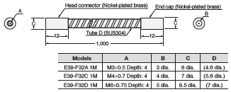
Protective Stainless Spiral Tube (Sold separately)
Insert the fiber cable into the protective tube to prevent breaking by snagging or shock.
| Applicable Fiber Units | Model | Quantity |
|---|---|---|
| E32-T11R 2M/E32-T11 2M/E32-LT11 2M/E32-LT11R 2M/ E32-T51R 2M/E32-T51 2M |
E39-F32C 1M | 2 pieces |
* This Tube cannot be used if a Lens Unit is being used.
Reflective Fiber Units
| Size | Appearance (mm) | Bending radius of cable | Sensing distance (mm) | Optical axis diameter (minimum sensing object) | Models | |
|---|---|---|---|---|---|---|
| E3X-HD | E3NX-FA | |||||
| 1.5 dia. |  IP67 IP67 |
Bend-resistant, R4 |
GIGA: 140 HS: 40 ST: 60 SHS: 16 |
GIGA: 210 HS: 60 ST: 90 SHS: 16 |
(5 μm dia./ 2 μm dia.) |
E32-D22B 2M |
| M3 |  IP67 IP67 |
E32-D21 2M | ||||
| 3 dia. |  IP67 IP67 |
GIGA: 300 HS: 90 ST: 140 SHS: 40 |
GIGA: 450 HS: 130 ST: 210 SHS: 40 |
E32-D221B 2M | ||
| M4 |  IP67 IP67 |
E32-D21B 2M | ||||
| M6 |  IP67 IP67 |
GIGA: 840 HS: 240 ST: 350 SHS: 100 |
GIGA: 1,260 HS: 360 ST: 520 SHS: 100 |
E32-D11 2M | ||
| Square |  IP67 IP67 |
GIGA: 240 HS: 60 ST: 100 SHS: 30 |
GIGA: 360 HS: 90 ST: 150 SHS: 30 |
E32-D25XB 2M | ||
[E3X-HD] GIGA: Giga-power mode (16 ms), HS: High-speed mode (250 μs), ST: Standard mode (1 ms), and
SHS: Super-high-speed mode (NPN output: 50 μs, PNP output: 55 μs)
[E3NX-FA] GIGA: Giga-power mode (16 ms), HS: High-speed mode (250 μs), ST: Standard mode (1 ms), and
SHS: Super-high-speed mode (30 μs)
2. The values for the minimum sensing object are reference values that indicate values obtained in standard mode
with the sensing distance and sensitivity set to the optimum values.
3. The first value is for the E3X-HD and the second value is for the E3NX-FA.
The sensing distances for Reflective Fiber Units are for white paper.
4. The sensing distances for the E3NX-FA are values for E3NX-FA[] devices. The distance for E3NX-FAH[] infrared
models varies.
Protective Stainless Spiral Tube (Sold separately)
Insert the fiber cable into the protective tube to prevent breaking by snagging or shock.
| Applicable Fiber Units | Models | Quantity |
|---|---|---|
| E32-D21R 2M/E32-C31 2M/E32-D21 2M | E39-F32A 1M | 1 piece |
| E32-D211R 2M/E32-D21B 2M | E39-F32C 1M | 2 pieces |
| E32-D11R 2M/E32-CC200 2M/E32-D11 2M/E32-D51R 2M/E32-D51 2M | E39-F32D 1M | 1 piece |
* This Tube cannot be used if a Lens Unit is being used.
Heat-resistant
Through-beam Fiber Units
| Heat- resistant temperature | Appearance (mm) | Bending radius of cable | Sensing distance (mm) | Optical axis diameter (minimum sensing object) | Models | |
|---|---|---|---|---|---|---|
| E3X-HD | E3NX-FA | |||||
| 100℃ *1 |  IP50 IP50 |
Flexible, R2 |
GIGA: 1,600 HS: 560 ST: 800 SHS: 225 |
GIGA: 2,400 HS: 840 ST: 1,200 SHS: 225 |
1 dia. (0.1 dia./ 0.03 dia.) |
E32-T51R 2M |
| 150℃ *2 |  IP67 IP67 |
R35 | GIGA: 2,800 HS: 1,000 ST: 1,500 SHS: 400 |
GIGA: 4,000 *5 HS: 1,500 ST: 2,250 SHS: 400 |
1.5 dia. (0.1 dia./ 0.03 dia.) |
E32-T51 2M |
| 200℃ *3 |  IP67 IP67 |
R10 | GIGA: 1,000 HS: 360 ST: 550 SHS: 140 |
GIGA: 1,500 HS: 540 ST: 820 SHS: 140 |
0.7 dia. (5 μm dia./ 2 μm dia.) |
E32-T81R-S 2M |
| 350℃ *4 |  IP67 IP67 |
R25 | GIGA: 1,680 HS: 600 ST: 900 SHS: 240 |
GIGA: 2,520 HS: 900 ST: 1,350 SHS: 240 |
1 dia. (5 μm dia./ 2 μm dia.) |
E32-T61-S 2M |
| 70℃ | - | Standard Fiber Units can be used. |
||||
*2 For continuous operation, use the Fiber Unit between −40 to 130°C.
*3 The heat-resistant rating is not the same for all parts of the Fiber Unit. Refer to the dimensions diagrams for details.
*4 The ambient operating temperature for the E32-T61-S 2M is −60 to 350°C.
*5 The optical fiber is 2 m long on each side, so the sensing distance is 4,000 mm.
Note 1. The following mode names and response times apply to the modes given in the Sensing distance column.
[E3X-HD] GIGA: Giga-power mode (16 ms), HS: High-speed mode (250 μs), ST: Standard mode (1 ms), and
SHS: Super-high-speed mode (NPN output: 50 μs, PNP output: 55 μs)
[E3NX-FA] GIGA: Giga-power mode (16 ms), HS: High-speed mode (250 μs), ST: Standard mode (1 ms), and
SHS: Super-high-speed mode (30 μs)
2. The values for the minimum sensing object are reference values that indicate values obtained in standard mode
with the sensing distance and sensitivity set to the optimum values.
The first value is for the E3X-HD and the second value is for the E3NX-FA.
3. The sensing distances for the E3NX-FA are values for E3NX-FA[] devices. The distance for E3NX-FAH[] infrared
models varies.
Reflective Fiber Units
| Heat- resistant temperature | Appearance (mm) | Bending radius of cable | Sensing distance (mm) | Standard sensing object (minimum sensing object) | Models | |
|---|---|---|---|---|---|---|
| E3X-HD | E3NX-FA | |||||
| 100℃ *1 |  IP50 |
Flexible, R2 |
GIGA: 670 HS: 190 ST: 280 SHS: 80 |
GIGA: 1,000 HS: 280 ST: 420 SHS: 80 |
(5 μm dia./ 2 μm dia.) |
E32-D51R 2M |
| 150℃ *2 |  IP67 |
R35 | GIGA: 1,120 HS: 320 ST: 450 SHS: 144 |
GIGA: 1,680 HS: 480 ST: 670 SHS: 144 |
E32-D51 2M | |
| 200℃ *3 |  IP67 |
R10 | GIGA: 420 HS: 120 ST: 180 SHS: 54 |
GIGA: 630 HS: 180 ST: 270 SHS: 54 |
E32-D81R-S 2M | |
| 300℃ |  IP30 |
R25 | GIGA: 10 to 20 HS: 10 to 20 ST: 10 to 20 SHS: - |
GIGA: 10 to 20 HS: 10 to 20 ST: 10 to 20 SHS: - |
Soda glass with reflection factor of 7% |
E32-A08H2 2M |
 IP40 |
GIGA: 20 to 30 HS: 20 to 30 ST: 20 to 30 SHS: - |
GIGA: 20 to 30 HS: 20 to 30 ST: 20 to 30 SHS: - |
End surface of soda glass with eflection factor of 7% (t = 0.7 mm, rounded edges) |
E32-A09H2 2M | ||
| 350℃ *3 |  IP67 |
GIGA: 420 HS: 120 ST: 180 SHS: 54 |
GIGA: 630 HS: 180 ST: 270 SHS: 54 |
(5 μm dia./ 2 μm dia.) |
E32-D611-S 2M | |
 |
GIGA: 420 HS: 120 ST: 180 SHS: 54 |
GIGA: 630 HS: 180 ST: 270 SHS: 54 |
E32-D61-S 2M | |||
| 400℃ *3 | Sleeve bending radius : 10 mm  |
GIGA: 280 HS: 80 ST: 120 SHS: 36 |
GIGA: 420 HS: 120 ST: 180 SHS: 36 |
E32-D73-S 2M | ||
| 70℃ | - | Standard Fiber Units can be used. |
||||
*2 For continuous operation, use the Fiber Unit between −40 to 130°C.
*3 The heat-resistant rating is not the same for all parts of the Fiber Unit. Refer to the dimensions diagrams for details.
Note 1. The following mode names and response times apply to the modes given in the Sensing distance column.
[E3X-HD] GIGA: Giga-power mode (16 ms), HS: High-speed mode (250 μs), ST: Standard mode (1 ms), and
SHS: Super-high-speed mode (NPN output: 50 μs, PNP output: 55 μs)
[E3NX-FA] GIGA: Giga-power mode (16 ms), HS: High-speed mode (250 μs), ST: Standard mode (1 ms), and
SHS: Super-high-speed mode (30 μs)
2. The values for the minimum sensing object are reference values that indicate values obtained in standard mode
with the sensing distance and sensitivity set to the optimum values.
The first value is for the E3X-HD and the second value is for the E3NX-FA.
3. The sensing distances for Reflective Fiber Units are for white paper.
4. The sensing distances for the E3NX-FA are values for E3NX-FA[] devices. The distance for E3NX-FAH[] infrared
models varies.
Special Applications
Area Beam (Area Detection)
Through-beam Fiber Units
| Type | Sensing width | Appearance (mm) | Bending radius of cable | Sensing distance (mm) | Optical axis diameter (minimum sensing object) | Models | |
|---|---|---|---|---|---|---|---|
| E3X-HD | E3NX-FA | ||||||
| Area | 11 mm |  IP50 |
Flexible, R1 |
GIGA: 3,100 HS: 1,120 ST: 1,700 SHS: 440 |
GIGA: 4,000 *1 HS: 1,680 ST: 2,550 SHS: 440 |
(0.2 dia./ 0.07 dia.) *2 |
E32-T16PR 2M |
 IP50 |
GIGA: 2,750 HS: 960 ST: 1,500 SHS: 380 |
GIGA: 4,000 *1 HS: 1,440 ST: 2,250 SHS: 380 |
E32-T16JR 2M | ||||
| 30 mm |  IP50 |
GIGA: 4,000 *1 HS: 1,700 ST: 2,600 SHS: 680 |
GIGA: 4,000 *1 HS: 2,550 ST: 3,900 SHS: 680 |
(0.3 dia./ 0.1 dia.) *2 |
E32-T16WR 2M | ||
| Array | 10 mm |  IP50 |
R5 | GIGA: 10 HS: 10 ST: 10 SHS: 10 |
GIGA: 10 HS: 10 ST: 10 SHS: 10 |
11 dia. | E32-G16 2M |
*2. The values for the minimum sensing object were obtained for detection in the sensing area with the sensing distance
set to 300 mm.
(The values are for a stationary sensing object.)
The first value is for the E3X-HD and the second value is for the E3NX-FA.
Note. The sensing distances for the E3NX-FA are values for E3NX-FA[] devices. The distance for E3NX-FAH[] infrared
models varies.
Reflective Fiber Units
| Type | Sensing width | Appearance (mm) | Bending radius of cable | Sensing distance (mm) | Optical axis diameter (minimum sensing object) | Models | |
|---|---|---|---|---|---|---|---|
| E3X-HD | E3NX-FA | ||||||
| Array | 11 mm |  IP67 IP67 |
Bend- resistant, R4 |
GIGA: 700 HS: 200 ST: 300 SHS: 90 |
GIGA: 1,050 HS: 300 ST: 450 SHS: 90 |
(5 μm dia./ 2 μm dia.) |
E32-D36P1 2M |
[E3X-HD] GIGA: Giga-power mode (16 ms), HS: High-speed mode (250 μs), ST: Standard mode (1 ms), and
SHS: Super-high-speed mode (NPN output: 50 μs, PNP output: 55 μs)
[E3NX-FA] GIGA: Giga-power mode (16 ms), HS: High-speed mode (250 μs), ST: Standard mode (1 ms), and
SHS: Super-high-speed mode (30 μs)
2. The values for the minimum sensing object are reference values that indicate values obtained in standard mode
with the sensing distance and sensitivity set to the optimum values.
The first value is for the E3X-HD and the second value is for the E3NX-FA.
3. The sensing distances for the E3NX-FA are values for E3NX-FA[] devices. The distance for E3NX-FAH[] infrared
models varies.
Liquid-level Detection
| Detection scheme | Tube diameter | Features | Appearance (mm) | Bending radius of cable | Applicable range | Optical axis diameter (minimum sensing object) | Models |
|---|---|---|---|---|---|---|---|
| Tube- mounting | 3.2, 6.4 and 9.5 dia. | Resistant to bubbles and droplets Residual quantity detection |
 IP50 IP50 |
Bend- resistant, R4 |
Applicable tube: Transparent tube with a diameter of 3.2, 6.4, or 9.5 dia. and a recommended wall thickness of 1 mm |
- | E32-A01 5M |
| 8 to 10 dia. | Ideal for mounting at multilevels |
 IP50 IP50 |
R10 | Applicable tube: Transparent tube with a diameter of 8 to 10 dia. and a recommended wall thickness of 1 mm |
- | E32-L25T 2M | |
| No restric- tions | Usable on large diameter tubes Resistant to bubbles and droplets |
 IP67 IP67 |
R4 | Applicable tube: Transparent tube (no restrictions on diameter) |
- | E32-D36T 2M | |
| Liquid contact (heat- resistant up to 200°C) | - | - |  IP68 IP68 |
R40 R25 *3 |
Liquid-contact Type *1 |
- | E32-D82F1 4M |
*2. The applicable range is the same whether an E3X-HD series or E3NX-FA series is used. This does not include E3NX-
FAH[] infrared models varies.
When using a Fiber Amplifier Unit in giga-power mode, level detection may not work depending on the tube diameter.
Make sure to confirm operation with the actual tube.
*3. The bending radius of the sensing section (except for the unbendable section) is 40 mm, and the bending radius of
the fiber is 25 mm.
Vacuum-resistant
Through-beam Fiber Units
| Type | Heat- resistant temperature | Appearance (mm) | Bending radius of cable | Sensing distance (mm) | Optical axis diameter (minimum sensing object) | Models | |
|---|---|---|---|---|---|---|---|
| E3X-HD | E3NX-FA | ||||||
| Vacuum side | 120℃ |  |
R30 | GIGA: 720 HS: 260 ST: 400 SHS: 100 |
GIGA: 1,080 HS: 390 ST: 600 SHS: 100 |
1.2 dia. (10 μm dia./ 4 μm dia.) |
E32-T51V 1M |
 |
GIGA: 2,000 * HS: 1,360 ST: 2,000 SHS: 520 |
GIGA: 2,000 * HS: 2,000 * ST: 2,000 * SHS: 520 |
4 dia. (0.1 dia./ 0.03 dia.) |
E32-T51V 1M + E39-F1V |
|||
| 200℃ |  |
R25 | GIGA: 1,760 HS: 640 ST: 950 SHS: 260 |
GIGA: 2,000 * HS: 960 ST: 1,420 SHS: 260 |
2 dia. (0.1 dia./ 0.03 dia.) |
E32-T84SV 1M | |
| Atmospheric pressure side | 70℃ |  |
- | - | - | E32-T10V 2M | |
Note 1. The following mode names and response times apply to the modes given in the Sensing distance column.
[E3X-HD] GIGA: Giga-power mode (16 ms), HS: High-speed mode (250 μs), ST: Standard mode (1 ms), and
SHS: Super-high-speed mode (NPN output: 50 μs, PNP output: 55 μs)
[E3NX-FA] GIGA: Giga-power mode (16 ms), HS: High-speed mode (250 μs), ST: Standard mode (1 ms), and
SHS: Super-high-speed mode (30 μs)
2. The values for the minimum sensing object are reference values that indicate values obtained in standard mode
with the sensing distance and sensitivity set to the optimum values.
The first value is for the E3X-HD and the second value is for the E3NX-FA.
3. The sensing distances for the E3NX-FA are values for E3NX-FA[] devices. The distance for E3NX-FAH[] infrared
models varies.
Flange
| Appearance | Type | Models |
|---|---|---|
 |
4-channel flange | E32-VF4 |
 |
1-channel flange | E32-VF1 |
FPD, Semiconductors, and Solar Cells
Limited-reflective Fiber Units
| Application | Ambient temper- ature | Appearance (mm) | Bending radius of cable | Sensing distance (mm) | Standard sensing object (minimum sensing object) | Models | |
|---|---|---|---|---|---|---|---|
| E3X-HD | E3NX-FA | ||||||
| Glass presence detection | 70℃ |  IP40 IP40 |
R25 | GIGA: 0 to 15 HS: 0 to 15 ST: 0 to 15 SHS: 0 to 12 |
GIGA: 0 to 15 HS: 0 to 15 ST: 0 to 15 SHS: 0 to 12 |
Soda glass with reflection factor of 7% |
E32-L16-N 2M *1 |
| Glass- substrate Alignment |
 IP40 IP40 |
GIGA: 10 to 20 HS: 10 to 20 ST: 10 to 20 SHS: - |
GIGA: 10 to 20 HS: 10 to 20 ST: 10 to 20 SHS: - |
E32-A08 2M *1 |
|||
| 300℃ |  IP30 IP30 |
E32-A08H2 2M *1 |
|||||
| 70℃ |  IP40 IP40 |
GIGA: 12 to 30 HS: 12 to 30 ST: 12 to 30 SHS: - |
GIGA: 12 to 30 HS: 12 to 30 ST: 12 to 30 SHS: - |
E32-A12 2M | |||
| Mapping of glass substrates |
 IP40 IP40 |
GIGA: 15 to 38 HS: 15 to 38 ST: 15 to 38 SHS: - (Center 25) |
GIGA: 15 to 38 HS: 15 to 38 ST: 15 to 38 SHS: - (Center 25) |
End surface of soda glass with reflection factor of 7% (t = 0.7 mm, rounded edges) |
E32-A09 2M | ||
| 300°C *2 |
 IP40 IP40 |
GIGA: 20 to 30 HS: 20 to 30 ST: 20 to 30 SHS: - (Center 25) |
GIGA: 20 to 30 HS: 20 to 30 ST: 20 to 30 SHS: - (Center 25) |
E32-A09H2 2M | |||
| Wet processes (Cleaning, Resist developing, and etching) | 60℃ |  IP67 IP67 |
R40 | 8 to 20 mm from tip of lens (Recommended sensing distance: 11 mm) 19 to 31 mm from center of mounting hole A (Recommended sensing distance: 22 mm) |
Glass (t=0.7mm) |
E32-L11FP 2M | |
| Wet processes (Resist stripping) | 85℃ |  IP67 IP67 |
8 to 20 mm from tip of lens (Recommended sensing distance: 11 mm) 32 to 44 mm from center of mounting hole A (Recommended sensing distance: 35 mm) |
E32-L11FS 2M | |||
*2 The maximum allowable temperature is not the same for all parts of the Fiber Unit. Refer to the dimensions diagrams
for details.
Must not be repeatedly subject to rapid temperature changes.
Note 1. The following mode names and response times apply to the modes given in the Sensing distance column.
[E3X-HD] GIGA: Giga-power mode (16 ms), HS: High-speed mode (250 μs), ST: Standard mode (1 ms), and
SHS: Super-high-speed mode (NPN output: 50 μs, PNP output: 55 μs)
[E3NX-FA] GIGA: Giga-power mode (16 ms), HS: High-speed mode (250 μs), ST: Standard mode (1 ms), and
SHS: Super-high-speed mode (30 μs)
2. The sensing distances for the E3NX-FA are values for E3NX-FA[] devices. The distance for E3NX-FAH[] infrared
models varies.
Through-beam Fiber Units
| Appli- cation | Ambient temper- ature | Aper- ture angle | Appearance (mm) | Bending radius of cable | Sensing distance (mm) | Optical axis diameter (minimum sensing object) | Models | |
|---|---|---|---|---|---|---|---|---|
| E3X-HD | E3NX-FA | |||||||
| Wafer Mapping | 70°C | 1.5° |  Thickness: 3 mm Thickness: 3 mm IP50 |
Flexible, R1 |
GIGA: 3,220 HS: 1,200 ST: 1,780 SHS: 500 |
GIGA: 4,000 * HS: 1,800 ST: 2,670 SHS: 500 |
2 dia. (0.1 dia./ 0.03 dia.) |
E32-A03 2M |
 Thickness: 3 mm Thickness: 3 mm IP50 |
R10 | E32-A03-1 2M | ||||||
| 3.4° |  Thickness: 2 mm Thickness: 2 mm IP50 |
GIGA: 1,280 HS: 450 ST: 680 SHS: 200 |
GIGA: 1,920 HS: 670 ST: 1,020 SHS: 200 |
1.2 dia. (0.1 dia./ 0.03 dia.) |
E32-A04 2M | |||
| 4° |  IP50 IP50 |
Flexible, R1 |
GIGA: 4,000 * HS: 1,460 ST: 2,200 SHS: 580 |
GIGA: 4,000 * HS: 2,190 ST: 3,300 SHS: 580 |
2 dia. (0.1 dia./ 0.03 dia.) |
E32-T24SR 2M | ||
| R10 | GIGA: 4,000 * HS: 1,740 ST: 2,600 SHS: 700 |
GIGA: 4,000 * HS: 2,610 ST: 3,900 SHS: 700 |
E32-T24S 2M | |||||
Note 1. The following mode names and response times apply to the modes given in the Sensing distance column.
[E3X-HD] GIGA: Giga-power mode (16 ms), HS: High-speed mode (250 μs), ST: Standard mode (1 ms), and
SHS: Super-high-speed mode (NPN output: 50 μs, PNP output: 55 μs)
[E3NX-FA] GIGA: Giga-power mode (16 ms), HS: High-speed mode (250 μs), ST: Standard mode (1 ms), and
SHS: Super-high-speed mode (30 μs)
2. The values for the minimum sensing object are reference values that indicate values obtained in standard mode
with the sensing distance and sensitivity set to the optimum values.
The first value is for the E3X-HD and the second value is for the E3NX-FA.
3. The sensing distances for the E3NX-FA are values for E3NX-FA[] devices. The distance for E3NX-FAH[] infrared
models varies.
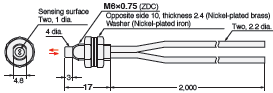
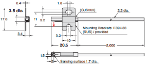
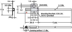
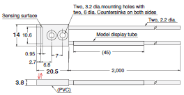
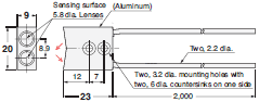
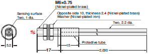
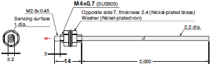
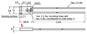
Dimensions | Fiber Sensors, Fiber Units - E32 Series
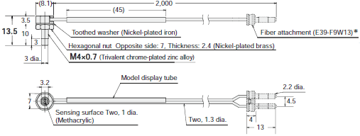
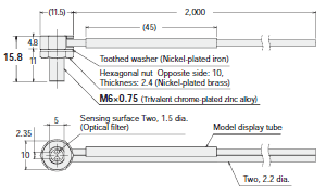
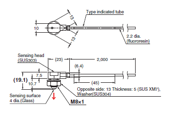
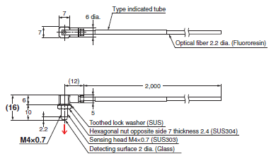
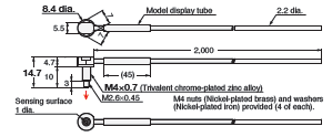
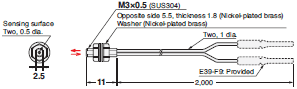
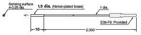
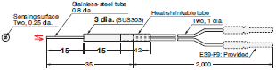
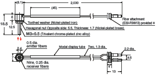
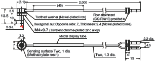
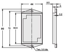
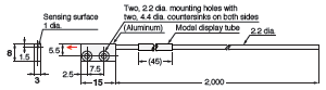
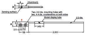
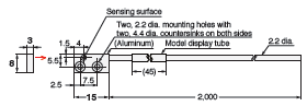
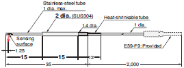
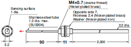
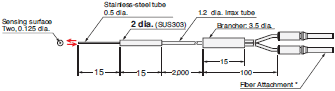
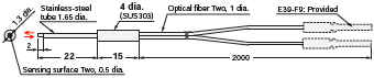
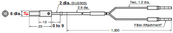
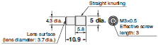
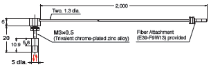
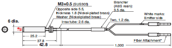
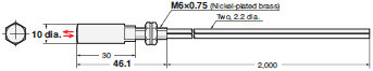
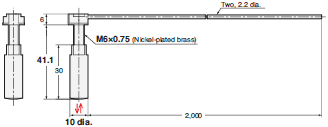
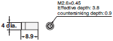
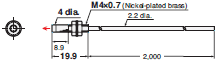
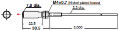
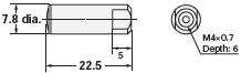
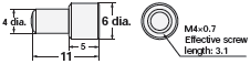
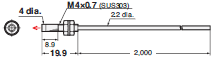
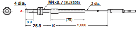
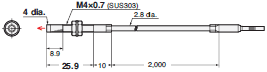
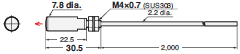
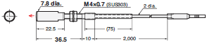
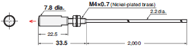
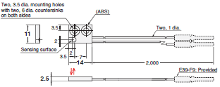
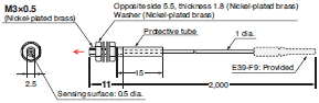
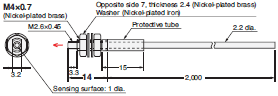
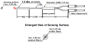
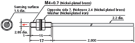
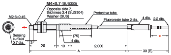
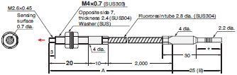
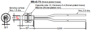
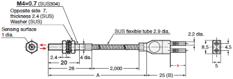
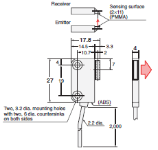
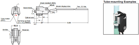
E32-T11N 2M (Free Cutting)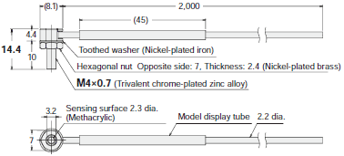
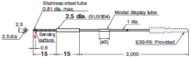
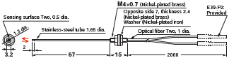
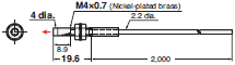
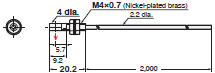
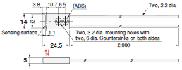
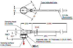
E32-T11R 2M (Free Cutting)
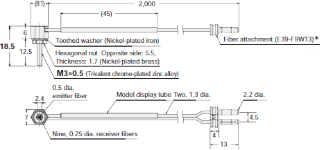
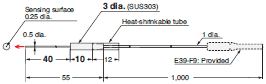
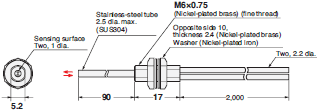
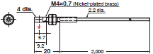
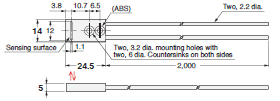
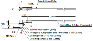
E32-LT11 2M (Free Cutting)
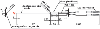
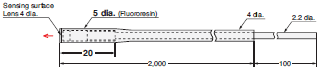
E32-LT11R 2M (Free Cutting)
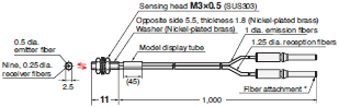
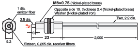
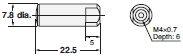
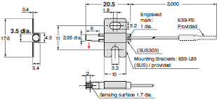
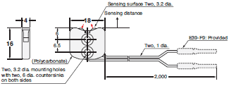
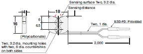
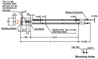
Reflective Fiber Units
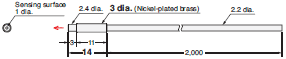
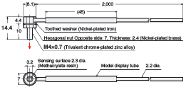
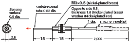
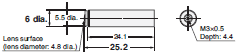
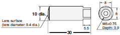
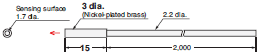
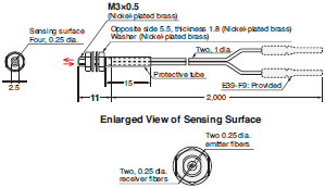
E32-C31N 2M (Free Cutting)
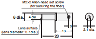
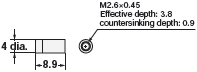
 Note: There is a white line on the emitter fiber.
 M3 nuts (Nickel-plated brass)
Washers (Nickel-plated brass) provided (2 of each)
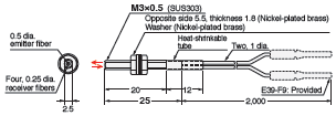
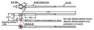
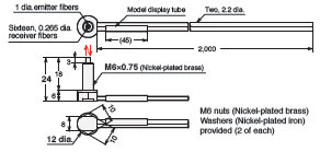
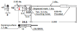
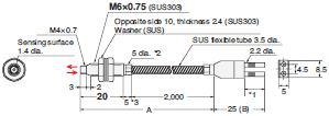
E32-C91N 2M (Free Cutting)
Note: There is a white line on the emitter fiber.
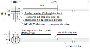
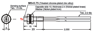
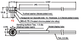
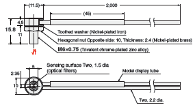
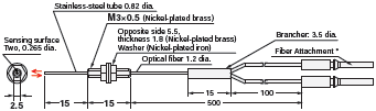
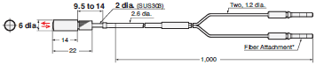
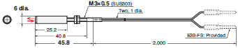
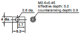
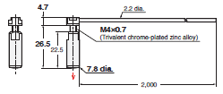
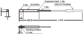
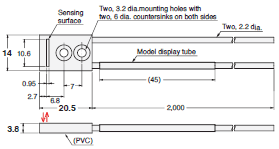
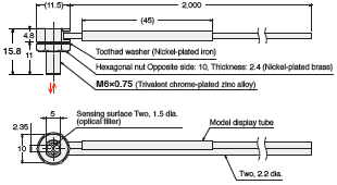
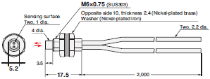
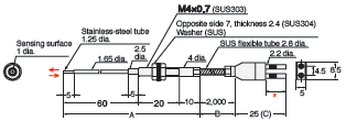
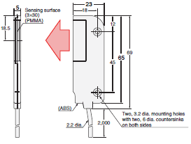
E32-D21R 2M (Free Cutting)
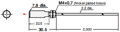
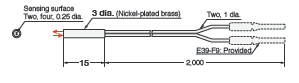
E32-C31 2M (Free Cutting)
Note: There is a white line on the emitter fiber.
E32-C31M 1M (Free Cutting)
 Note: There is a white line on the emitter fiber.
 * The Fiber Attachments that are provided were specially designed for this Fiber Unit.
E39-F9 cannot be attached.
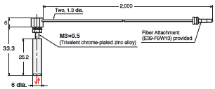
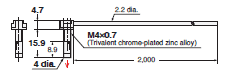
E32-D211R 2M (Free Cutting)
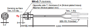
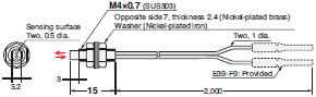
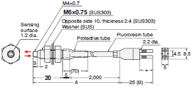
E32-D11R 2M (Free Cutting)
E32-CC200 2M (Free Cutting)
Note: There is a white line on the emitter fiber.
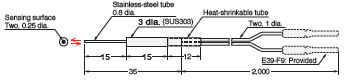
E32-LD11 2M (Free Cutting)
E32-LD11R 2M (Free Cutting)
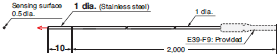
Cylindrical Models
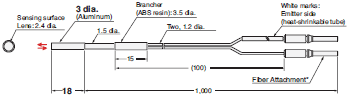
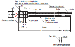
Through-beam Fiber Units (Set of 2)
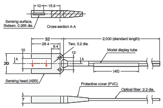
E32-T223R 2M (Free Cutting)
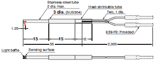
E32-T22B 2M (Free Cutting)
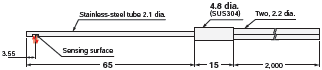
E32-T12R 2M (Free Cutting)
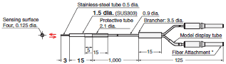
E32-T14LR 2M (Free Cutting)
Reflective Fiber Units
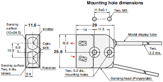
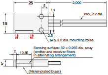
E32-D22B 2M (No Cutting)
* Attached with adhesive and cannot be removed.
E32-D43M 1M (No Cutting)
* Attached with adhesive and cannot be removed.
E32-D22R 2M (Free Cutting)
E32-D221B 2M (Free Cutting)
E32-D32L 2M (Free Cutting)
Note: There is a yellow dotted line on the Emitter fiber.
E32-D33 2M (Free Cutting)
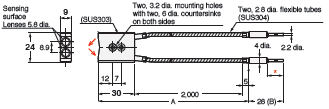
Hex-shaped Models
Through-beam Fiber Units
E32-LT11N 2M (Free Cutting)
E32-T11N 2M (Free Cutting)
Reflective Fiber Units
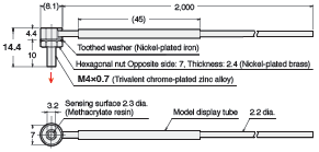
E32-LD11N 2M (Free Cutting)
E32-C21N 2M (Free Cutting)
 Note: There is a white line on the emitter fiber.
 * Applicable Fiber Amplifier Units: E3NX-FA, E3NX-CA, E3X-HD, and E3X-DA-S.
Use the enclosed E39-F9-7 Fiber Attachment for other models, such as the E3X-MDA with two channels, and for the E3X-
SD, E3X-NA, and other models that have an 8-mm space between the emitter and receiver fiber insertion holes.
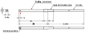
E32-D21N 2M (Free Cutting)
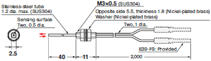
 * Applicable Fiber Amplifier Units: E3NX-FA, E3NX-CA, E3X-HD, and E3X-DA-S.
 Use the enclosed E39-F9-7 Fiber Attachment for other models, such as the E3X-MDA with two channels, and for the E3X-
SD, E3X-NA, and other models that have an 8-mm space between the emitter and receiver fiber insertion holes.
E32-C11N 2M (Free Cutting)
Note: There is a white line on the emitter fiber.
Retro-reflective Fiber Units (With M.S.R. Function)
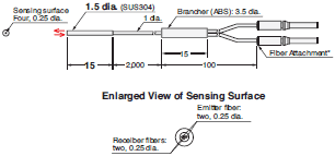
E32-LR11NP 2M (Free Cutting)
E39-RP1
Material:
[Reflective surface] Methacrylate resin
[Back] ABS
Saving Space
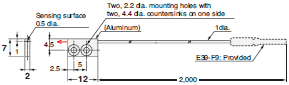
Flat Models
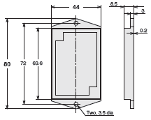
Through-beam Fiber Units (Set of 2)
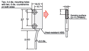
E32-T15XR 2M (Free Cutting)
 Note: 1. Set of two symmetrically shaped Fiber Units.
 2. Four, M2 × 8 stainless steel countersunk mounting screws are provided.
E32-T15YR 2M (Free Cutting)
 Note: 1.Set of two symmetrically shaped Fiber Units.
 2. Four, M2 × 8 stainless steel countersunk mounting screws are provided.
E32-T15ZR 2M (Free Cutting)
 Note: 1. Set of two symmetrically shaped Fiber Units.
 2. Four, M2 × 8 stainless steel countersunk mounting screws are provided.
E32-LT35Z 2M (Free Cutting)
Note: 1. Set of two symmetrically shaped Fiber Units.
2. Four, M2 x 8 stainless-steel, pan-head mounting screws,
four spring washers, four flat washers, and four nuts are provided.
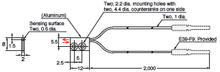
Reflective Fiber Units
E32-D15XR 2M (Free Cutting)
Note: Two, M2 × 8 stainless steel countersunk mounting screws are provided.
E32-D15YR 2M (Free Cutting)
Note: Two, M2 × 8 stainless steel countersunk mounting screws are provided.
E32-D15ZR 2M (Free Cutting)
Note: Two, M2 × 8 stainless steel countersunk mounting screws are provided.
Sleeve Models (Close-range Detection)
Through-beam Fiber Units (Set of 2)
E32-T24R 2M (Free Cutting)
E32-T24E 2M (Free Cutting)
E32-T33 1M (Free Cutting)
E32-T21-S1 2M (Free Cutting)
E32-TC200BR 2M (Free Cutting)
Reflective Fiber Units
E32-D24R 2M (Free Cutting)
E32-D24-S2 2M (Free Cutting)
E32-D43M 1M (No Cutting)
* Attached with adhesive and cannot be removed.
E32-D331 2M (No Cutting)
* Attached with adhesive and cannot be removed.
E32-D33 2M (Free Cutting)
E32-D32-S1 0.5M (No Cutting)
* Attached with adhesive and cannot be removed.
E32-D31-S1 0.5M (No Cutting)
* Attached with adhesive and cannot be removed.
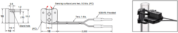
E32-DC200F4R 2M (Free Cutting)
E32-D22-S1 2M (Free Cutting)
E32-D21-S3 2M (Free Cutting)
E32-DC200BR 2M (Free Cutting)
E32-D25-S3 2M (Free Cutting)
Beam Improvements
Small-Spot, Reflective (Minute Object Detection)
Reflective Fiber Units
E32-C42 1M (No Cutting) + E39-F3A

* Attached with adhesive and cannot be removed.
Note: There is a white tube on the emitter fiber.
E39-F3A
Material: Aluminum for body and optical glass for lens.
Note: This is the Lens Unit for the E32-C42.
E32-C42 1M (No Cutting) + E39-F17
* Attached with adhesive and cannot be removed.
Note: There is a white tube on the emitter fiber.
E39-F17
Material: Aluminum for body and optical glass for lens.
E32-C31 2M (Free Cutting) + E39-F3C
Note: There is a white line on the emitter fiber.
E39-F3C
Material: Aluminum for body and optical glass for lens.
Note: This is the Lens Unit for the E32-C31 and E32-C31N.
E32-C21N 2M (Free Cutting) + E39-F3C
Note: There is a white line on the emitter fiber.
E32-C42S 1M (No Cutting)
* Attached with adhesive and cannot be removed.
Note: There is a white tube on the emitter fiber.
E32-L15 2M (Free Cutting)
Note: There is a white tube on the emitter fiber.
E32-C41 1M (No Cutting) + E39-F3A-5
* Attached with adhesive and cannot be removed.
Note: There is a white tube on the emitter fiber.
E39-F3A-5

Material: Aluminum for body and optical glass for lens
Note: This is a Lens Unit for the E32-C41, E32-C31 and E32-C31N.
E32-C31 2M (Free Cutting) + E39-F3A-5
Note: There is a white line on the emitter fiber.
E32-C21N 2M (Free Cutting) + E39-F3A-5
Note: There is a white line on the emitter fiber.
E32-C41 1M (No Cutting) + E39-F3B
* Attached with adhesive and cannot be removed.
Note: There is a white tube on the emitter fiber.
E39-F3B
Material: Aluminum for body and optical glass for lens
Note: This is a Lens Unit for the E32-C41, E32-C31 and E32-C31N.
E32-C31 2M (Free Cutting) + E39-F3B
Note: There is a white line on the emitter fiber.
E32-C21N 2M (Free Cutting) + E39-F3B
Note: There is a white line on the emitter fiber.
E32-CC200 2M (Free Cutting) + E39-F18
Note: There is a white line on the emitter fiber.
E39-F18
Material: Aluminum for body and optical glass for lens
Note: This is a Lens Unit for the E32-C91N and E32-CC200.
E32-C91N 2M (Free Cutting) + E39-F18
Note: There is a white line on the emitter fiber.
High-power Beam (Long-distance Installation, Dust-resistant)
Fiber only
Through-beam Fiber Units (Set of 2)
E32-LT11N 2M (Free Cutting)
E32-T17L 10M (Free Cutting)
E32-LT11 2M (Free Cutting)
E32-LT11R 2M (Free Cutting)
E32-T14 2M (Free Cutting)
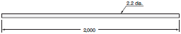
Reflective Fiber Units
E32-D16 2M (Free Cutting)
Lens (to 70°C)
Lens Units (Set of 2)
E39-F1
Material: Brass for the body and optical glass for the lens itself.
Note: Two per set.
E39-F16
Material: SUS303 for the body and optical glass for the lens itself.
Note: Two per set.
E39-F2
Material: Brass for the body and optical glass for the lens itself.
Note: Two per set.
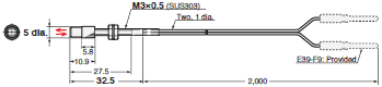
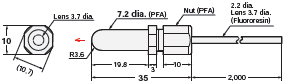
Through-beam Fiber Units (Set of 2)
E32-T11N 2M (Free Cutting) + E39-F1
E32-T11R 2M (Free Cutting) + E39-F1
E32-T11 2M (Free Cutting) + E39-F1
E32-T11N 2M (Free Cutting) + E39-F16
E32-T11R 2M (Free Cutting) + E39-F16
E32-T11 2M (Free Cutting) + E39-F16
E32-T11R 2M (Free Cutting) + E39-F2
E32-T11 2M (Free Cutting) + E39-F2
Lens (to 200°C)
Lens Units (Set of 2)
E39-F1
Material: Brass for the body and optical glass for the lens itself.
Note: Two per set.
E39-F16
Material: SUS303 for the body and optical glass for the lens itself.
Note: Two per set.
E39-F2
Material: Brass for the body and optical glass for the lens itself.
Note: Two per set.
E39-F1-33
Material: Brass for the body and optical glass for the lens itself.
Note 1: Two per set.
Note 2: This is the Lens Unit for the E32-T51.
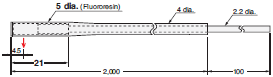
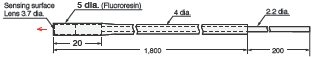
Through-beam Fiber Units (Set of 2)
E32-T51R 2M (Free Cutting) + E39-F1
E32-T81R-S 2M (No Cutting) + E39-F1
E32-T61-S 2M (No Cutting) + E39-F1
E32-T51R 2M (Free Cutting) + E39-F16
E32-T81R-S 2M (No Cutting) + E39-F16
E32-T61-S 2M (No Cutting) + E39-F16
E32-T51R 2M (Free Cutting) + E39-F2
E32-T81R-S 2M (No Cutting) + E39-F2
E32-T61-S 2M (No Cutting) + E39-F2
E32-T51 2M (Free Cutting) + E39-F1-33
E32-T51 2M (Free Cutting) + E39-F16
Narrow View (Detection Across clearance)
Through-beam Fiber Units (Set of 2)
E32-A03 2M (Free Cutting)
Note: Use the engraved surface and its opposing surface as installation (reference) surfaces.
E32-A03-1 2M (Free Cutting)
 Note 1. Use the engraved surface and its opposing surface as installation (reference) surfaces.
 2. Set of two symmetrically shaped Fiber Units.
E32-A04 2M (Free Cutting)
Note: Use the engraved surface and its opposing surface as installation (reference) surfaces.
E32-T24SR 2M (Free Cutting)
E32-T24S 2M (Free Cutting)

E32-T22S 2M (Free Cutting)
Detection without Background Interference
Limited-reflective Fiber Units
E32-L16-N 2M (Free Cutting)
E32-L24S 2M (Free Cutting)
E32-L25L 2M (Free Cutting)
Transparent Object Detection
Retro-reflective
Retro-reflective Fiber Units (With M.S.R. Function)
E32-LR11NP 2M (Free Cutting)
E39-RP1
Material:
[Reflective surface] Methacrylate resin
[Back] ABS
E32-R16 2M (Free Cutting)
E39-R1 (Provided)
Material:
[Reflective surface] Methacrylate resin
[Back] ABS
E32-R21 2M (Free Cutting)
E39-R3 (Provided)
Material:
[Reflective surface] Methacrylate resin
[Back] ABS
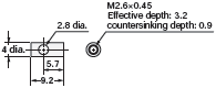
Limited-reflective (Glass Detection)
Limited-reflective Fiber Units
E32-L24S 2M (Free Cutting)
E32-L16-N 2M (Free Cutting)
E32-A08 2M (Free Cutting)
E32-A12 2M (Free Cutting)
E32-L25L 2M (Free Cutting)

E32-A09 2M (Free Cutting)
Environmental Immunity
Chemical-resistant, Oil-resistant
Through-beam Fiber Units (Set of 2)
E32-T11NF 2M (Free Cutting)
E32-T11NFS 2M (Free Cutting)
E32-T12F 2M (Free Cutting)
E32-T11F 2M (Free Cutting)
E32-T14F 2M (Free Cutting)
E32-T51F 2M (Free Cutting)
Reflective Fiber Units
E32-L11FP 2M (Free Cutting)
E32-L11FS 2M (Free Cutting)
E32-D12F 2M (Free Cutting)
E32-D11U 2M (Free Cutting)
Bending-resistant, Disconnection-resistant
Through-beam Fiber Units (Set of 2)
E32-T22B 2M (Free Cutting)
E32-T21 2M (Free Cutting)
E32-T11 2M (Free Cutting)
E32-T25XB 2M (Free Cutting)
 Note 1. Set of two symmetrically shaped Fiber Units.
 2. Four, M2 × 8 stainless steel countersunk mounting screws are provided.
E39-F32C 1M
Note: Saddles (four, trivalent chromate-plated iron) are provided.
Limited-reflective Fiber Units
E32-D22B 2M (No Cutting)
* Attached with adhesive and cannot be removed.
E32-D21 2M (Free Cutting)
E32-D221B 2M (Free Cutting)
E32-D21B 2M (Free Cutting)
E32-D11 2M (Free Cutting)
E32-D25XB 2M (Free Cutting)
Note: Two, M2×8 stainless steel countersunk mounting screws are provided.
E39-F32A 1M/E39-F32C 1M/E39-F32D 1M
Note: Saddles (two (four for the E39-F32C 1M), trivalent chromate-plated iron) are provided.
Heat-resistant
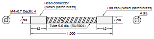
Through-beam Fiber Units (Set of 2)
E32-T51R 2M (Free Cutting)
E32-T51 2M (Free Cutting)
E32-T81R-S 2M (No Cutting)
Note: The maximum allowable temperatures for sections A and B are 200°C and 110°C, respectively. The section inserted into the Amplifier Unit (indicated by *) must be maintained within the Amplifier Unit's operating temperature range.
E32-T61-S 2M (No Cutting)
Note: The maximum allowable temperatures for sections A and B are 350°C and 110°C, respectively. The section inserted into the Amplifier Unit (indicated by *) must be maintained within the Amplifier Unit's operating temperature range.
Reflective Fiber Units
E32-D51R 2M (Free Cutting)
E32-D51 2M (Free Cutting)
E32-D81R-S 2M (No Cutting)
Note: The maximum allowable temperatures for sections A and B are 200°C and 110°C, respectively. The section inserted into the Amplifier Unit (indicated by *) must be maintained within the Amplifier Unit's operating temperature range.
E32-A08H2 2M (No Cutting)
Note: The maximum allowable temperatures for sections A and B are 300°C and 110°C, respectively.
E32-A09H2 2M (No Cutting)
Note: The maximum allowable temperatures for sections A and B are 300°C and 110°C, respectively. The section inserted into the Amplifier Unit (indicated by *) must be maintained within the Amplifier Unit's operating temperature range.
E32-D611-S 2M (No Cutting)
Note: The maximum allowable temperatures for sections A and B are 350°C and 110°C, respectively.
The section inserted into the Amplifier Unit (indicated by *) must be maintained within the Amplifier Unit's operating temperature range.
E32-D61-S 2M (No Cutting)
Note: The maximum allowable temperatures for sections A and B are 350°C and 110°C, respectively. The section inserted into the Amplifier Unit (indicated by *1) must be maintained within the Amplifier Unit's operating temperature range.
*2. The diameter is 6 dia. if the fiber length exceeds 10 m.
*3. The length is 10 if the fiber length exceeds 10 m.
E32-D73-S 2M (No Cutting)
Note: The maximum allowable temperatures for sections A, B, and C are 400°C, 300°C, and 110°C, respectively. The section inserted into the Amplifier Unit (indicated by *) must be maintained within the Amplifier Unit's operating temperature range.
Special Applications
Area Beam (Area Detection)
Through-beam Fiber Units (Set of 2)
E32-T16PR 2M (Free Cutting)
* Stickers with slits of widths 0.5 and 1 mm (2 of each) provided.
E32-T16JR 2M (Free Cutting)
E32-T16WR 2M (Free Cutting)
E32-G16

Reflective Fiber Units
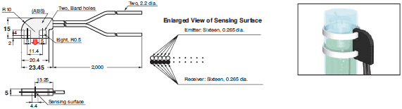
E32-D36P1 2M (Free Cutting)
Liquid-level Detection
E32-A01 5M (Free Cutting)
* Mount the holder at the appropriate position based on the actual tube diameter (1/8, 1/4, 3/8 inch).
Note: Two nylon bands are provided.
E32-L25T 2M (Free Cutting)
Note: Two nylon bands and one anti-reflector are provided.
E32-D36T 2M (Free Cutting)
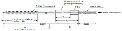
E32-D82F1 4M (Free Cutting)
* The 2-m section of optical fiber on the Amplifier unit side is plastic and therefore allows free cutting.
Note: The maximum allowable temperature is 200°C for section A and 85°C for section B.
Vacuum-resistant
Through-beam Fiber Units (Set of 2)
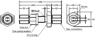
E32-T51V 1M (No Cutting)
E32-T51V 1M (No Cutting) + E39-F1V
E39-F1V
E32-T84SV 1M (No Cutting)
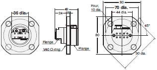
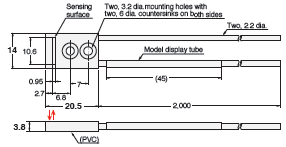
E32-T10V 2M (Free Cutting)
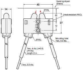
E32-VF4
Note 1. Mount the Flange so that the V40 O-ring is on the atmospheric-pressure side of the vacuum chamber wall.
Note 2. Mounting-hole dimensions: 38 dia. ±0.5 mm
Note 3. The maximum tightening torque is 9.8 Nm.
Note 4. A V40 O-ring is provided.
E32-VF1
Note 1. Mount the Flange so that the V15 O-ring is on the atmospheric-pressure side of the vacuum chamber wall.
Note 2. Mounting-hole dimensions: 14.5 dia. ±0.2 mm
Note 3. The maximum tightening torque is 14.7 Nm for the clamp nut and 1.5 Nm for the connector.
Note 4. A V15 O-ring, nut, spring washer, two connectors, and four O-rings for the fibers are provided.
FPD, Semiconductors, and Solar Cells
Limited-reflective Fiber Units
E32-L16-N 2M (Free Cutting)
E32-A08 2M (Free Cutting)
E32-A08H2 2M (No Cutting)
Note: The maximum allowable temperatures is 300°C for sections A and 110°C for section B (section inserted into Amplifier Unit).
E32-A12 2M (Free Cutting)
E32-A09 2M (Free Cutting)
E32-A09H2 2M (No Cutting)
Note: The maximum allowable temperatures for sections A and B are 300°C and 110°C, respectively. The section inserted into the Amplifier Unit (indicated by *) must be maintained within the Amplifier Unit's operating temperature range.
E32-L11FP 2M (Free Cutting)
E32-L11FS 2M (Free Cutting)
Through-beam Fiber Units (Set of 2)
E32-A03 2M (Free Cutting)
Note: Use the engraved surface and its opposing surface as installation (reference) surfaces.
E32-A03-1 2M (Free Cutting)
Note 1. Use the engraved surface and its opposing surface as installation (reference) surfaces.
Note 2. Set of two symmetrical parts.
E32-A04 2M (Free Cutting)
Note: Use the engraved surface and its opposing surface as installation (reference) surfaces.
E32-T24SR 2M (Free Cutting)
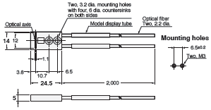
E32-T24S 2M (Free Cutting)
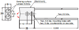
Features | Fiber Sensors, Fiber Units - E32 Series
OMRON's Fiber Sensors continue to support an increasing range of applications. E32-T11NF[] Fiber Units for Reliable, Stable Operation in Cutting Oil Environments. E32-LT11N / LD11N / LR11NP Fiber Units with Build-in Lenses provide more stable detection and simpler, more reliable installation.
Properties | Fiber Sensors, Fiber Units - E32 Series
| Fiber Units Sensors | E32 Series |
|---|---|
| Type | Variable spot, Parallel, light Short-distance, Long-distance, Small-spot, Oil resistant, Chemical resistant, Area, Array, Vacuum side, Atmospheric pressure side |
| Spot diameter (∅) | 0.1 to 0.6, 0.3 to 1.6, 4, 0.1, 0.2, 0.3, 0.5 |
| Size | ∅ 1,∅ 1.2, ∅ 1.5, ∅1.7, ∅ 2, ∅ 3, ∅3.8, M3, M4, M6, Square |
| Bending radius of cable | Bend-resistance, Flexible, R1, R4, R10, R25, R40 |
| Optical axis diameter () | 0.25, 0.5, 1, 2.3, 3, 4, 7.2, 11 |
ไฟเบอร์เซนเซอร์ - E32 Series
ไฟเบอร์เซนเซอร์ของ OMRON ยังคงรองรับการใช้งานที่หลากหลายมากขึ้น
ดาวน์โหลดไฟล์ PDF คุณสมบัติ | ไฟเบอร์เซนเซอร์ - E32 Series
- ตัวโครงสร้างเป็นสแตนเลสทั้งหมด
- การตรวจจับระยะไกล เท่ากันหรือมากกว่าเซนเซอร์แบบหัวเรซิ่น
- มีความทนทานมากกว่า Proximity Sensors ที่มีหัวเรซิ่น 20 เท่า
- รุ่นป้องกันการกระเด็นใช้การเคลือบด้วยฟูลออโรเรซิ่น
- ชิพอลูมิเนียมป้องกัน
- นอกจากนี้ยังมีรุ่นเชื่อมต่อสมาร์ทคลิ๊กแบบมีสาย
ข้อมูลจำเพาะ | ไฟเบอร์เซนเซอร์ - E32 Series
| Fiber Units Sensors | E32 Series |
|---|---|
| ประเภท | จุดแปรผัน, ขนาน, แสงระยะสั้น, ระยะไกล, จุดเล็ก, ทนน้ำมัน, ทนสารเคมี, พื้นที่, อาร์เรย์, ด้านข้างสูญญากาศ, ด้านข้างความดันบรรยากาศ, เส้นผ่านศูนย์กลางของจุด |
| เส้นผ่านศูนย์กลางของจุด (∅) | 0.1 to 0.6, 0.3 to 1.6, 4, 0.1, 0.2, 0.3, 0.5 |
| ขนาด | ∅ 1,∅ 1.2, ∅ 1.5, ∅1.7, ∅ 2, ∅ 3, ∅3.8, M3, M4, M6, สี่เหลี่ยม |
| รัศมีการดัดของสายเคเบิล | ทนต่อการโค้งงอ, ยืดหยุ่น, R1, R4, R10, R25, R40 |
| เส้นผ่านศูนย์กลางแกนออฟติก (∅) | 0.25, 0.5, 1, 2.3, 3, 4, 7.2, 11 |


 Your Lift