
OMRON Emergency Stop Switches - A165E
Emergency Stop Switches - A165E series
Download PDF
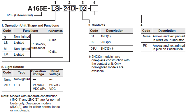
Model Numbers | Emergency Stop Switches - A165E series
List of Models
| Diameter of Operation Unit | Function | Model | Shape | |
|---|---|---|---|---|
| 30-mm models 40-mm models |
Push-Lock, turn-reset | A165E | Separate construction |  (30-mm model) |
| A165E-[]-03U | One-piece construction |  (30-mm model) |
||
Model Number Legend (Completely Assembled)
Shipped as a set that includes the Operation Unit and light source.
List of Sets
| Illumination | Rated voltage | Pushbutton color | Pushbutton size | Terminal | Contact form | Model |
|---|---|---|---|---|---|---|
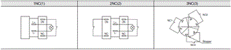
| LED | 24 VAC/VDC | Red | 30 dia. | Solder terminal | 1NC(1) | A165E-LS-24D-01 |
| A165E-LS-24D-01-PK | ||||||
| 2NC(2) | A165E-LS-24D-02 | |||||
| A165E-LS-24D-02-PK | ||||||
| Non-lighted | --- | 1NC(1) | A165E-S-01 | |||
| A165E-S-01-PK | ||||||
| 2NC(2) | A165E-S-02 | |||||
| A165E-S-02-PK | ||||||
| LED | 24 VAC/VDC | 40 dia. | 1NC(1) | A165E-LM-24D-01 | ||
| A165E-LM-24D-01-PK | ||||||
| 2NC(2) | A165E-LM-24D-02 | |||||
| A165E-LM-24D-02-PK | ||||||
| Non-lighted | --- | 1NC(1) | A165E-M-01 | |||
| A165E-M-01-PK | ||||||
| 2NC(2) | A165E-M-02 | |||||
| A165E-M-02-PK | ||||||
| Non-lighted | --- | 30 dia. | 3NC(3) | A165E-S-03U | ||
| A165E-S-03U-PK | ||||||
| 40 dia. | A165E-M-03U | |||||
| A165E-M-03U-PK |
List of Sets (in Different Colors)
| Illumination | Pushbutton color * | Pushbutton size | Terminal | Contact form | Model |
|---|---|---|---|---|---|
| Non-lighted | Yellow | 30 dia. | Solder terminal | 1NC(1) | A165E-SY-01 |
| Gray | A165E-SGR-01 | ||||
| Yellow | 2NC(2) | A165E-SY-02 | |||
| Gray | A165E-SGR-02 | ||||
| Yellow | 3NC(3) | A165E-SY-03U | |||
| Gray | A165E-SGR-03U |
* Models with yellow or gray pushbutton colors cannot be used as emergency switches.
Individual Parts (for Switches with Separate Construction)
Operation Units
| Appearance | Illumination | Model | |
|---|---|---|---|
| 30 dia. |  |
Non-lighted | A165E-S |
| A165E-S-PK | |||
| Lighted | A165E-LS | ||
| A165E-LS-PK | |||
| 40 dia. |  |
Non-lighted | A165E-M |
| A165E-M-PK | |||
| Lighted | A165E-LM | ||
| A165E-LM-PK | |||
Lamps
| Appearance | LED color | Rated voltage | Model | |
|---|---|---|---|---|
 |
Red | Bright | 5 VDC | A16-5DSR |
| 12 VAC/VDC | A16-12DSR | |||
| 24 VAC/VDC | A16-24DSR | |||
Switches
| Appearance | Illumination | Contact form | Model |
|---|---|---|---|
 |
Non-lighted | 1NC(1) | A165E-01 |
| 2NC(2) | A165E-02 | ||
| Lighted | 1NC(1) | A165E-01L | |
| 2NC(2) | A165E-02L |
Switch Units
| Appearance | Illumination | Contact form | Model |
|---|---|---|---|
 |
Lighted | 1NC(1) | A165E-R-24D-01 |
| 2NC(2) | A165E-R-24D-02 |
Accessories (Order Separately)
| Item | Appearance | Type | Model | Precautions |
|---|---|---|---|---|
| Yellow Plate |  |
Yellow, 45 dia. | A16Z-5070 | Use this as an emergency stop nameplate. |
| Panel Plug |  |
Round | A16ZT-3003 | Used for covering the panel cutouts for future panel expansion. Degree of protection: IP40 Color: Black |
| Tightening Tool |  |
--- | A16Z-3004 | Useful for repetitive mounting. Be careful not to tighten excessively. |
| Extractor |  |
A16Z-5080 | Convenient for extracting the Switch and Lamp. | |
Specifications | Emergency Stop Switches - A165E series
Certified Standard Ratings
UL508, CSA C22.2 No.14, CCC(GB14048.5)
Models with Separate Construction
| Rated voltage | Resistive load |
|---|---|
| 125 VAC 250 VAC 30 VDC |
5 A 3 A 3 A |
Models with One-piece Construction
| Rated voltage | Resistive load |
|---|---|
| 125 VAC 250 VAC 30 VDC |
1 A 0.5 A 1 A |
TÜV (EN60947-5-1)
Models with Separate Construction
| Rated voltage | Resistive load |
|---|---|
| 250 VAC 30 VDC |
3 A 3 A |
Models with One-piece Construction
| Rated voltage | Resistive load |
|---|---|
| 250 VAC 30 VDC |
0.5 A 1 A |
Certified Standards
| Certification body | Standards | File No. |
|---|---|---|
| UL * | UL508, CSA C22.2 No.14 |
E76675 |
| TÜV SÜD | EN60947-5-1 (certified direct opening), EN60947-5-5 |
Consult your OMRON representative for details. |
| CQC (CCC) | GB14048.5 | 2003010303070678 |
* Certification for CSA C22.2 No. 14 has been obtained. Separate construction models have been certified for the Switch
Unit.
Switch Ratings
Models with Separate Construction
| Rated voltage | Resistive load |
|---|---|
| 125 VAC 250 VAC 30 VDC |
5 A 3 A 3 A |
Note: Minimum applicable load: 5 VDC, 150 mA
Models with One-piece Construction
| Rated voltage | Resistive load |
|---|---|
| 125 VAC 250 VAC 30 VDC |
1 A 0.5 A 1 A |
Note: Minimum applicable load: 5 VDC, 1 mA
LED Ratings (Only for Models with LEDs)
| Rated voltage | Rated current | Operation voltage |
|---|---|---|
| 24 VAC/VDC | 8 mA | 24 VAC/VDC±5% |
Characteristics
| Type | Emergency Stop Switch | |||
|---|---|---|---|---|
| Non-lighted A165E-S/A165E-M | Lighted A165E-LS/A165-LM | Non-lighted, One-piece construction A165E-U | ||
| Allowable operating frequency | Mechanical | 20 operations/minute max. | ||
| Electrical | 10 operations/minute max. | |||
| Insulation resistance | 100 MΩ min. (at 500 VDC) | |||
| Dielectric strength | Between terminals of same polarity | 1,000 VAC, 50/60 Hz for 1 min | ||
| Between terminals of different polarity | 2,000 VAC 50/60 Hz for 1 min | |||
| Between each terminal and ground | 2,000 VAC 50/60 Hz for 1 min | |||
| Between lamp terminals | 1,000 VAC, 50/60 Hz for 1 min *1 | --- | ||
| Vibration resistance | Malfunction | 10 to 55 Hz, 1.5-mm double amplitude (malfunction within 1 ms) | ||
| Shock resistance | Destruction | 500 m/s2 | ||
| Malfunction | 300 m/s2 max. (malfunction within 1 ms) |
150 m/s2 max. (malfunction within 1 ms) |
||
| Durability | Mechanical | 100,000 operations min. | ||
| Electrical | 100,000 operations min. | |||
| Degree of protection | IP65 Oil-resistant *2 | IP65 *2 | IP65 Oil-resistant *2 | |
| Electric shock protection class | Class II | |||
| PTI (tracking characteristic) | 175 | |||
| Degree of contamination | 3 (EN60947-5-1) | |||
| Weight | Approx. 16 g (in case of 2NC(2) Switches) | |||
| Ambient operating temperature | -10 to 55°C (with no icing or condensation) | |||
| Ambient operating humidity | 35% to 85% | |||
| Ambient storage temperature | -25 to 65°C (with no icing or condensation) | |||
*1. LED not mounted. (Test them with the LED removed.)
*2. Degree of protection from the front of the panel.
Operating Characteristics
| Type | Characteristics of models with separate construction | Characteristics of models with one-piece construction |
|---|---|---|
| Operating force OF max. | 14.7 N | 14.7 N |
| Releasing torque RF max. | 0.1 Nm | 0.1 Nm |
| Pretravel PT | 3.5±0.5 mm | 3±0.5 mm |
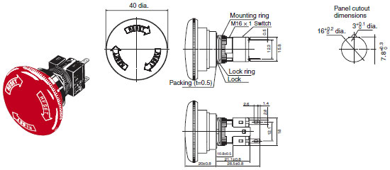
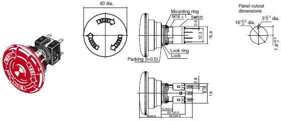
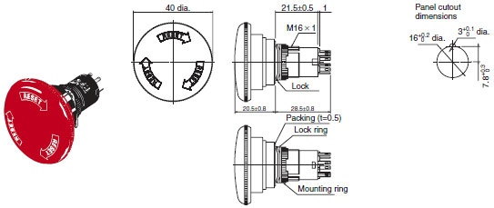
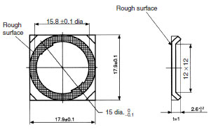
Dimensions | Emergency Stop Switches - A165E series
(Unit: mm)
A165E-S
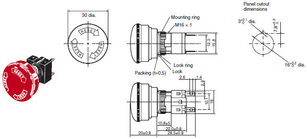 ・ When applying a coating such as paint to the panel, dimensions after the coating must satisfy the specified
 dimensions.
・ Recommended panel thickness: 0.5 to 3.2 mm.
A165E-LS
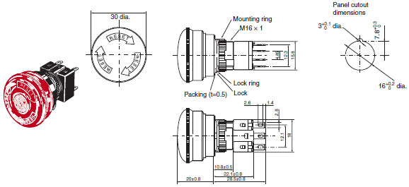 ・ When applying a coating such as paint to the panel, dimensions after the coating must satisfy the specified
 dimensions.
・ Recommended panel thickness: 0.5 to 3.2 mm.
A165E-S-03U
Non-lighted,
One-piece construction models 30 mm diameter
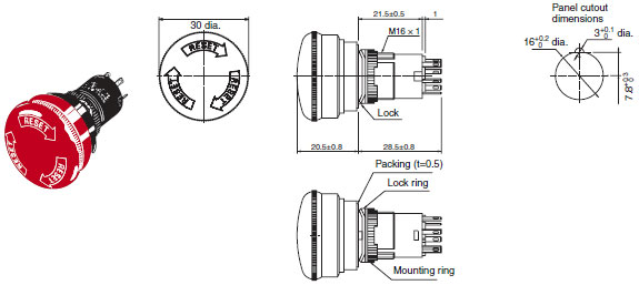 ・ When applying a coating such as paint to the panel, dimensions after the coating must satisfy the specified
 dimensions.
・ Recommended panel thickness: 0.5 to 3.2 mm.
A165E-M
Non-lighted models
40 mm diameter
 ・ When applying a coating such as paint to the panel, dimensions after the coating must satisfy the specified
 dimensions.
・ Recommended panel thickness: 0.5 to 3.2 mm.
A165E-LM
Lighted models
40 mm diameter
 ・ When applying a coating such as paint to the panel, dimensions after the coating must satisfy the specified
 dimensions.
・ Recommended panel thickness: 0.5 to 3.2 mm.
A165E-M-03U
One-piece construction models
40 mm diameter
・ When applying a coating such as paint to the panel, dimensions after the coating must satisfy the specified
dimensions.
・ Recommended panel thickness: 0.5 to 3.2 mm.
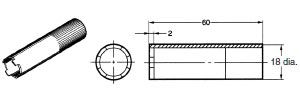
Accessories
Yellow Plate (Vinyl Chloride) A16Z-5070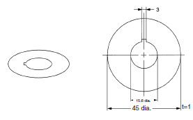
Lock Ring
Panel Plugs (Round Type)
A16ZT-3003

Select an appropriate Panel Plug according to the panel design and mount from the front side of the panel. Panel cutout dimensions are the same as those for the Operation Unit.
Tightening Tool
A16Z-3004
Terminal Arrangement
Note: The L+ and L− terminals are not available with the non-lighted models.
Features | Emergency Stop Switches - A165E series
- Direct opening mechanism to open contacts in emergencies
- Conforms to EN 60947-5-5.
- Models available with 3 contacts built into a single block.
Properties | Emergency Stop Switches - A165E series
| Emergency Stop Switches | A165E series |
|---|---|
| Direct opening force | 14.7 N |
| Operation Unit Shape and Function | 16 dia |
| Weight | Approx 16 g (DPST-NC Switches) |
| Contacts | SPST-NC / DPST-NC / TPST-NC |
| Degree of protection | IP65 / 69K |
| Head Dimensions | Diameter 30 / 40 mm |
Emergency Stop Switches - A165E
ดาวน์โหลดไฟล์ PDF คุณสมบัติ | Emergency Stop Switches - A165E series
- กลไกการเปิดโดยตรง เพื่อเปิดหน้าสัมผัสในกรณีฉุกเฉิน
- ตามมาตรฐาน EN 60947-5-5
- โมเดลที่สามารถใช้ 3 หน้าสัมผัสภายในบล็อกเดียว
ข้อมูลจำเพาะ | Emergency Stop Switches - A165E series
| Emergency Stop Switches | A165E series |
|---|---|
| แรงกระทำน้อยสุดต่อหน้าสัมผัส | 14.7 นิวตัน |
| เส้นผ่านศูนย์กลางของรูยึด | 16 dia |
| น้ำหนัก | ประมาณ 16 กรัม (DPST-NC Switches) |
| รูปแบบหน้าสัมผัส | SPST-NC / DPST-NC / TPST-NC |
| มาตรฐานการป้องกัน | IP65 / 69K |
| ขนาดของหัวสวิตซ์ | เส้นผ่านศูนย์กลาง 30 / 40 mm |


 Your Lift