
OMRON Safety Door Switches - D4GS-N
Safety Door Switches - D4GS-N series
Download PDF
Model Numbers | Safety Door Switches - D4GS-N series
Switches (Operation Keys are sold separately.)
Consult with your OMRON representative when ordering any models that are not listed in this table.
| Appearance | Direction of Operation Key insertion | Cable length | 1NC/1NO (Slow-action) | 2NC (Slow-action) | 2NC/1NO (Slow-action) | 3NC (Slow-action) |
|---|---|---|---|---|---|---|
 |
Horizontal | 1 m | D4GS-N1R | D4GS-N2R | D4GS-N3R | D4GS-N4R |
| 3 m | D4GS-N1R-3 | D4GS-N2R-3 | D4GS-N3R-3 | D4GS-N4R-3 | ||
| 5 m | D4GS-N1R-5 | D4GS-N2R-5 | D4GS-N3R-5 | D4GS-N4R-5 | ||
 |
Vertical | 1 m | D4GS-N1T | D4GS-N2T | D4GS-N3T | D4GS-N4T |
| 3 m | D4GS-N1T-3 | D4GS-N2T-3 | D4GS-N3T-3 | D4GS-N4T-3 | ||
| 5 m | D4GS-N1T-5 | D4GS-N2T-5 | D4GS-N3T-5 | D4GS-N4T-5 |
Operation Keys
| Type | Model | |
|---|---|---|
| Horizontal mounting |  |
D4GS-NK1 |
| Vertical mounting |  |
D4GS-NK2 |
| Adjustable mounting (Vertical upward) |  |
D4GS-NK4 |
| Adjustable mounting (Vertical downward) |  |
D4GS-NK4-2 |
Specifications| Safety Door Switches - D4GS-N series
Standards and EC Directives
Conforms to the following EC Directives:
• Machinery Directive
• Low Voltage Directive
• EN ISO 14119
• EN60204-1
• GS-ET-15
Certified Standards
| Certification body | Standard | File No. |
|---|---|---|
| TÜV SÜD | EN60947-5-1 (certified direct opening) |
Consult your OMRON representative for details. |
| UL * | UL508 CSA C22.2 No. 14 |
E76675 |
| CQC (CCC) | GB/T 14048.5 | Consult your OMRON representative for details. |
* Certification for CSA C22.2 No. 14 is authorized by the UL mark.
Certified Standard Ratings
TÜV (EN60947-5-1), CCC (GB/T 14048.5)
| Utilization category | AC-15 | DC-13 |
|---|---|---|
| Rated operating current (Ie) | 0.75 A | 0.27 A |
| Rated operating voltage (Ue) | 240 V | 250 V |
Note: Use a 10 A fuse type gI or gG that conforms to IEC60269 as a short-circuit protection device.
UL/CSA (UL508, CSA C22.2 No. 14)
C300
| Rated voltage | Carry current | Current (A) | Volt-amperes (VA) | ||
|---|---|---|---|---|---|
| Make | Break | Make | Break | ||
| 120 VAC | 2.5 A | 15 | 1.5 | 1,800 | 180 |
| 240 VAC | 7.5 | 0.75 | |||
Q300
| Rated voltage | Carry current | Current (A) | Volt-amperes (VA) | ||
|---|---|---|---|---|---|
| Make | Break | Make | Break | ||
| 125 VDC | 2.5 A | 0.55 | 0.55 | 69 | 69 |
| 250 VDC | 0.27 | 0.27 | |||
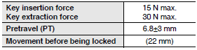
Characteristics
| Interlock type | Type 2 (EN ISO 14119) | |
|---|---|---|
| Coding level | Low level coded (EN ISO 14119) | |
| Degree of protection *1 | IP67 (EN60947-5-1) | |
| Durability *2 | Mechanical | 1,000,000 operations min. |
| Electrical | 100,000 operations min. (1 A resistive load at 125 VAC) *3 | |
| Operating speed | 0.1 to 0.5 m/s | |
| Operating frequency | 30 operations/minute max. | |
| Direct opening force *4 | 60 N min. | |
| Direct opening travel *4 | 10 mm min. | |
| Contact resistance | 300 mΩ max. (with 1 m cable) 500 mΩ max. (with 3 m cable) 700 mΩ max. (with 5 m cable) |
|
| Minimum applicable load *5 | Resistive load of 4 mA at 24 VDC (N-level reference value) | |
| Rated insulation voltage (Ui) | 250 V | |
| Rated frequency | 50/60 Hz | |
| Protection against electric shock | Class II (double insulation) | |
| Pollution degree (operating environment) | 3 (EN60947-5-1) | |
| Impulse withstand voltage (Uimp) (EN60947-5-1) | Between terminals of same polarity | 2.5 kV |
| Between terminals of different polarity |
4 kV | |
| Between each terminal and non- current carrying metallic parts |
6 kV | |
| Insulation resistance | 100 MΩ min. (at 500 VDC) between terminals of the same polarities, between terminals of different polarities, and between each terminal and non-current carrying metal parts |
|
| Contact gap | 2 × 2 mm min. | |
| Vibration resistance | Malfunction | 10 to 55 Hz, 0.35 mm single amplitude |
| Shock resistance | Destruction | 1,000 m/s2 min. |
| Malfunction | 300 m/s2 min. | |
| Conditional short-circuit current | 100 A (EN60947-5-1) | |
| Conventional free air thermal current (Ith) | 2.5 A (EN60947-5-1) | |
| Ambient operating temperature | -30 to 70°C (with no icing) | |
| Ambient operating humidity | 95% max. | |
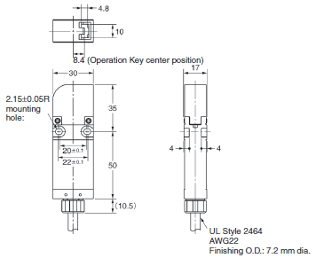
| Cable | UL2464 No. 22 AWG, finishing O.D.: 7.2 mm | |
| Weight | Approx. 120 g (D4GS-N1R, with 1 m cable) | |
Note: 1. The above values are initial values.
2. The Switch contacts can be used with either standard loads or microloads. Once the contacts have been used to
switch a load, however, they cannot be used to switch smaller loads. The contact surfaces will become rough
once they have been used and contact reliability for smaller loads may be reduced.
*1. The degree of protection shown above is based on the test method specified in EN60947-5-1. Be sure to confirm in
advance the sealing performance under the actual operating environment and conditions.
Although the switch box is protected from dust, oil, or water penetration, do not use the D4GS-N in places where dust,
oil,water, or chemicals may enter through the key hole on the head, otherwise Switch damage or malfunctioning may
occur.
*2. The durability conditions are an ambient temperature of 5 to 35°C and an ambient humidity of 40% to 70%. For more
details, consult your OMRON representative.
*3. When the ambient temperature is 35°C or higher, do not apply 1 A at 125 VAC to more than one circuit.
*4. These figures are minimum requirements for safe operation.
*5. The value given for minimum applicable load is a reference value for microloads. The value will vary depending on
factors such as the switching frequency, the ambient environment, and the reliability level. Be sure to confirm correct
operation with the actual load before application.
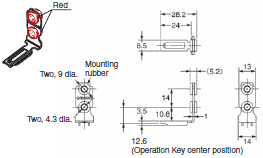
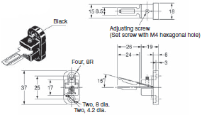
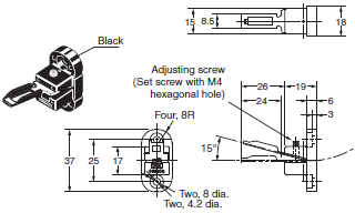
Dimensions | Safety Door Switches - D4GS-N series
Note: Unless otherwise specified, a tolerance of ±0.4 mm applies to all dimensions. Dimensions in parentheses are
reference values.
Switches
D4GS-N[]R-[]
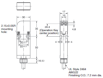
D4GS-N[]T-[]
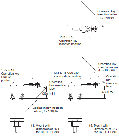
Operating characteristics
Note: There are fluctuations in the contact ON/OFF timing for Switches with multiple poles (2NC, 2NC/1NO, or 3NC).
Confirm performance before application.
Operation Keys
D4GS-NK1
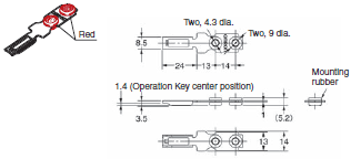
D4GS-NK2
D4GS-NK4
D4GS-NK4-2
With Operation Key Inserted
</D4GS-N[]R-[] + D4GS-NK1
D4GS-N[]T-[] + D4GS-NK1
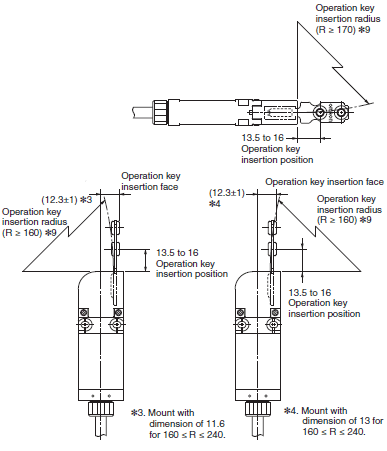
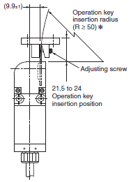
D4GS-N[]R-[] + D4GS-NK2
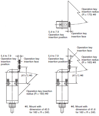
D4GS-N[]T-[] + D4GS-NK2
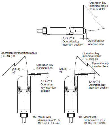
*9. Insertion radii apply when the rotational center of the Operation Key is in line with a line extending from the front or top Head surface.
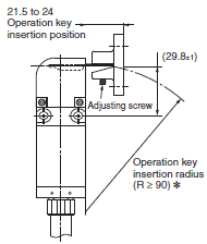
D4GS-N[]R-[] + D4GS-NK4
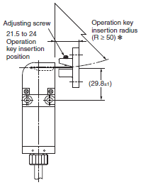
Note 1. When determining the operation key insertion radius, adjust the adjusting screw so that the tip of the operation
key is positioned to the center of the key insertion hole of the Switch.
2. The operation key cannot be inserted or adjusted in a direction different from the one shown above.
Use the D4GS-NK1 or D4GS-NK2 if necessary.
D4GS-N[]T-[] + D4GS-NK4
Note 1. When determining the operation key insertion radius, adjust the adjusting screw so that the tip of the operation
key is positioned to the center of the key insertion hole of the Switch.
2. The operation key cannot be inserted or adjusted in a direction different from the one shown above.
Use the D4GS-NK1 or D4GS-NK2 if necessary.
D4GS-N[]R-[] + D4GS-NK4-2
D4GS-N[]T-[] + D4GS-NK4-2
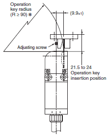
* Insertion radii apply when the rotational center of the Operation Key is in line with a line extending from the front or top Head surface.
Features | Safety Door Switches - D4GS-N series
- Slim design with a width of only 17 mm (three-contact models).
- Reversible design allowing either front or rear mounting.
- Built-in Switches with two- or three-terminal contact construction are available.
- Operation Key with rubber mounting hole to absorb vibration and shock.
- IP67 degree of protection.
Properties | Safety Door Switches - D4GS-N series
| Safety Door Switches | D4GS-N |
|---|---|
| Direct opening force | 60 N |
| Max Actuation Frequency | 30 operations / min |
| Max Actuation Speed | 500 mm / s |
| Weight | Approx 120 g |
| Built-in Switch | 1 NO/1 NC, 2 NC, 2 NC/1 NO, 3 NC (Slow-action) |
| Degree of protection | IP67 |
| Dimensions (W x L x H) mm | 85 x 30 x 17 |
Safety Door Switches - D4GS-N series
ดาวน์โหลดไฟล์ PDF คุณสมบัติ | Safety Door Switches - D4GS-N series
- ออกแบบให้บาง มีความกว้าง 17 มิลลิเมตร (โมเดล 3 หน้าสัมผัส)
- ออกแบบให้สามารถติดตั้งด้านหน้าหรือด้านหลังได้
- ติดตั้งสวิตซ์มีหน้าสัมผัส 2 หรือ 3 เทอร์มินอล
- หน้าสัมผัสมียางยึดช่วยดูดซับแรงสั่นสะเทือน และแรงกระแทก
ข้อมูลจำเพาะ | Safety Door Switches - D4GS-N series
| Safety Door Switches | D4GS-N |
|---|---|
| แรงกระทำน้อยสุดต่อหน้าสัมผัส | 60 นิวตัน |
| ความถี่สูงสุดในการทำงาน | 30 การประมวล / นาที |
| ความเร็วสูงสุดในการทำงาน | 500 มิลลิเมตร / วินาที |
| น้ำหนัก | ประมาณ 120 กรัม |
| รูปแบบหน้าสัมผัส | 1 NO/1 NC, 2 NC, 2 NC/1 NO, 3 NC (Slow-action) |
| มาตรฐานการป้องกัน | IP67 |
| ขนาด (W x L x H) mm | 85 x 30 x 17 |


 Your Lift