
OMRON Counter - H7BX
Counter - H7BX
Donwload PDF
Model Numbers | Counter - H7BX
| External power supply | Output type | Supply voltage | 1-stage | 2-stage |
|---|---|---|---|---|
| 12 VDC | Contact and NPN transistor output |
100 to 240 VAC | H7BX-A | H7BX-AW |
| 24 VAC/12 to 24 VDC | H7BX-AD1 | H7BX-AWD1 |
Accessories (Order Separately)
| Name | Model |
|---|---|
| Soft Cover | Y92A-72F1 |
| Hard Cover | Y92A-72 |
| Terminal Cover * | Y92A-72T |
* Supplied with the H7BX.
Specifications | Counter - H7BX
Ratings
| Model | H7BX-A/AD1 | H7BX-AW/AWD1 | |
|---|---|---|---|
| Type | Preset counter | Preset counter/tachometer | |
| Supported configurations | 1-stage preset counter, total and preset counter *1 (selectable) |
1-stage preset counter, 2-stage preset counter, total and preset counter (*1), batch counter, dual counter, tachometer (selectable) |
|
| Ratings | Power supply voltage *2 |
H7BX-A/AW: 100 to 240 VAC (50/60 Hz) H7BX-AD1/AWD1: 24 VAC (50/60 Hz)/12 to 24 VDC (ripple 20% max.) |
|
| Operating voltage range |
85% to 110% of rated supply voltage (90% to 110% at 12 VDC) | ||
| Power consumption | H7BX-A/AW: 9.6 VA max. (100 to 240 VAC) H7BX-AD1/AWD1: 8 VA max. (24 VAC), 5.3 W max. (12 to 24 VDC) |
||
| Mounting method | Flush mounting | ||
| External connections | Screw terminals | ||
| Degree of protection | IP54 (front section only) | ||
| Input signals | CP1, CP2, reset 1, reset 2, key protection | ||
| Counter | Max. counting speed | 30 Hz or 5 kHz (selectable, ON/OFF ratio 1:1), setting for both CP1 and CP2 | |
| Input modes | Increment, decrement, command (UP/DOWN A), individual (UP/DOWN B), quadrature (UP/DOWN C) |
||
| Output modes | N, F, C, R, K-1, P, Q, A, K-2, D, L | N, F, C, R, K-1, P, Q, A, K-2, D, L, H | |
| One-shot output time | 0.01 to 99.99 s | ||
| Reset input | External reset (minimum reset input signal width: 1 ms or 20 ms selectable), manual reset, and automatic reset (internal according to C, R, P, and Q mode operation) |
||
| Tachometer | Pulse measurement method |
--- | Periodic measurement (Sampling period: 200 ms) |
| Max. counting speed | --- | 30 Hz or 10 kHz (selectable) | |
| Measuring ranges | --- | 30 Hz: 0.01 to 30.00 Hz 10 kHz: 0.01 Hz to 10 kHz |
|
| Measuring accuracy | --- | ±0.1% FS ±1 digit max. (at 23 ±5°C) | |
| Output modes | --- | Upper and lower limits, area, upper limit, lower limit |
|
| Auto-zero time | --- | 0.1 to 99.9 s | |
| Startup time | --- | 0.0 to 99.9 s | |
| Average processing | --- | OFF/2/4/8 times | |
| Prescaling function | Yes (0.001 to 99.999) | ||
| Decimal point adjustment | Yes (rightmost 3 digits) | ||
| Sensor waiting time | 290 ms max. (Control output is turned OFF and no input is accepted during sensor waiting time.) |
||
| Key protection input | Response speed: Approx. 1 s No-voltage NPN input (fixed) Short-circuit (ON) impedance: 1 kΩ max. (Leakage current at 0 Ω: Approx. 12 mA) Short-circuit (ON) residual voltage: 3 V max. Open (OFF) impedance: 100 kΩ min. |
||
| Input method (except key protection input) |
No-voltage NPN input or voltage PNP input (selectable) No-voltage input Short-circuit (ON) impedance: 1 kΩ max. (Leakage current at 0 Ω: Approx. 12 mA) Short-circuit (ON) residual voltage: 3 V max. Open (OFF) impedance: 100 kΩ min. Voltage input High level: 4.5 to 30 VDC Low level: 0 to 2 VDC Input resistance: Approx. 4.7 kΩ |
||
| External power supply | 12 VDC (±10%), 100 mA (For details, refer to External Power Supply on Data Sheet.) |
||
| Control output | Contact output: 3 A at 250 VDC/30 VDC, resistive load (cosφ = 1) Minimum applied load: 10 mA at 5 VDC (Failure level: P, reference value) Transistor output: 100 mA max. at 30 VDC max. Residual voltage: 1.5 VDC max. (approx. 1 V) Leakage current: 0.1 mA max. |
||
| Display *3 | Backlit 7-segment negative transmissive LCD Character Heights PV: 13.5 mm (red/green) SV: 9 mm (green) |
||
| Digits | 6 digits -99,999 to 999,999 (5 digits negative and 6 digits positive) |
6 digits Counter: -99,999 to 999,999 (5 digits negative and 6 digits positive) Tachometer: 0 to 999,999 (6 digits) |
|
| Memory backup | EEPROM (Overwrites: 100,000 min.), Data storage: 10 years min. | ||
| Ambient operating temperature | -10 to 55°C (with no icing) | ||
| Ambient storage temperature | -25 to 65°C (with no icing) | ||
| Ambient operating humidity | 25 to 85°C (with no condensation) | ||
| Case color | Black (N1.5) | ||
| Accessories | Two flush-mounting adapters, terminal cover |
Two flush-mounting adapters, terminal cover, DIP switch setting stickers |
|
*1. The total and preset counter functions as a 1-stage preset counter and total counter.
*2. Do not use an inverter output for the power supply.
*3. Displayed only when the power is ON. Not displayed when the power is OFF.
Characteristics
| Insulation resistance | 100 MΩ min. (at 500 VDC) between current-carrying terminal and exposed non-current-carrying metal parts, and between non-continuous contacts |
|---|---|
| Dielectric strength | Between current-carrying metal parts and non-current-carrying metal parts: 2,000 VAC, 50/60 Hz for 1 min Between power supply and input circuit: 2,000 VAC, 50/60 Hz for 1 min (for models other than the H7BX-A[]D1) 1,000 VAC, 50/60 Hz for 1 min (H7BX-A[]D1) Between control output, power supply, and input circuit: 2,000 VAC, 50/60 Hz for 1 min Between non-continuous contacts: 1,000 VAC, 50/60 Hz for 1 min |
| Impulse withstand voltage | Between power terminals: 3.0 kV (1.0 kV for 24 VAC/12 to 24 VDC models) Between current-carrying terminal and exposed non-current-carrying metal parts: 4.5 kV (1.5 kV for 24 VAC/12 to 24 VDC models) |
| Noise immunity | Between power terminals: ±1.5 kV Between input terminals: ±600 V Square-wave noise by noise simulator (Pulse width: 100 ns/1 μs, 1-ns rise) |
| Static immunity | Malfunction: 8 kV Destruction: 15 kV |
| Vibration resistance | Destruction: 10 to 55 Hz, 0.75-mm single amplitude, 2 hours each in three directions Malfunction: 10 to 55 Hz, 0.50-mm single amplitude, 10 minutes each in three directions |
| Shock resistance | Destruction: 294 m/s2 3 times each in 6 directions Malfunction: 98 m/s2 3 times each in 6 direction |
| Life expectancy | Mechanical: 10,000,000 operations min. Electrical: 100,000 operations min. (3 A at 250 VAC/30 VDC, resistive load) * |
| Weight | Approx. 250 g |
* Check the electrical life expectancy curve.
Electrical Life Expectancy (Reference Values)
Resistive Load
Inductive Load
A current of 0.15 A max. can be switched at 125 VDC (cosφ = 1) and current of 0.1 A max. can be switched with L/R = 7 m/s. In both cases, a life of 100,000 operations can be expected.
Applicable Standards
| Approved safety standards |
cURus: UL 508, CSA C22.2 No. 14 EN 61010-1 (IEC 61010-1): Pollution degree 2/overvoltage category II; EN 61326; VDE 0106 Part 100 |
|---|---|
| EMC | (EMI) EN 61326-1 * Emission Enclosure: EN 55011 Group 1 class A Emission AC mains: EN 55011 Group 1 class A (EMS) EN 61326-1 * Immunity ESD: EN 61000-4-2: 4 kV contact discharge; 8 kV air discharge Immunity RF-interference: EN 61000-4-3: 10 V/m (Amplitude-modulated, 80 MHz to 1 GHz); 10 V/m (Pulse- modulated, 900 MHz ±5 MHz) Immunity Conducted Disturbance: EN 61000-4-6: 3 V (0.15 to 80 MHz) Immunity Burst: EN 61000-4-4: 2 kV power-line; 1 kV I/O signal-line Immunity Surge: EN 61000-4-5: 1 kV line to lines (power and output lines (relay outputs)); 2 kV line to ground (power and output lines (relay outputs)) Immunity Voltage Dip/Interruption: EN 61000-4-11: 0.5 cycle, 100% (rated voltage) |
* Industrial electromagnetic environment (EN/IEC 61326-1 Table 2)
I/O Functions
Using as a Counter *1
| Inputs | CP1, CP2 | (1) All Modes Except for Dual Counter Mode Reads count signals. Increment, decrement, up/down (command, individual, or quadrature) inputs can be used. (2) Dual Counter Mode Reads CP1 count signals on CP1 input and CP2 count signals on CP2 input. Increment signals can be used. |
|---|---|---|
| Reset or Reset 1 |
(1) All Modes Except for Dual Counter Mode Resets present value and outputs (OUT2 when using the batch counter). *2 Counting cannot be performed while resetting or when reset 1 input is ON. The reset indicator is lit while the reset input is ON. (2) Dual Counter Mode Resets the CP1 present value to 0. Counting the CP1 input cannot be performed while the reset 1 input is ON. The reset indicator is lit while the reset 1 input is ON. |
|
| Total Reset or Reset 2 |
The reset operation depends on the selected function. *3 | |
| Outputs | OUT1, 2 | When the corresponding set value is reached, signals are output according to the designated output mode. |
*1. Refer to Data Sheet for information on the operation of input and output functions.
*2. In increment mode or increment/decrement mode, the present value returns to 0; in decrement mode, the present value returns to the set value with 1-stage models, and returns to set value 2 with 2-stage models.
*3. The reset indicator will not be lit when the total reset or reset 2 input is ON.
| Function | Reset operation |
|---|---|
| 1-stage/2-stage preset counter | Does not operate (Not used). |
| Total and preset counter | Resets the total count value. Holds the total count value at 0 while the total reset input is ON. |
| Batch counter | Resets the batch count value and batch output (OUT1). Holds the batch count value at 0 while the reset 2 input is ON. |
| Dual counter | Resets the CP2 present value. Counting for CP2 input is disabled while the reset 2 input is ON. |
Using as a Tachometer
| Inputs | CP1, CP2 | Reads counting signals. (CP2 input is not available.) |
|---|---|---|
| Reset 1, Reset 2 |
Holds the measurement value and outputs. (Reset 2 input is not available.) The reset indicator is lit during hold. |
|
| Outputs | OUT1, 2 | Outputs signals according to the specified output mode when a set value is reached. |
Using as a Counter or Tachometer
| Key protection input | Prohibits using the keys on the front panel. Set the key protection level in function selection mode. Key protection is enable by short-circuited key protection terminals. |
|---|
Note: For details, refer to Data Sheet.
Dimensions | Counter - H7BX
Counter
Counter
H7BX-A[][]
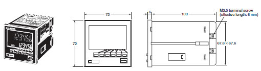
Note: M3.5 terminal screws (effective length: 6 mm).
Dimensions with Flush Mounting Adapter
H7BX-A[][]
(The flush mounting adapter is supplied with the H7BX.)
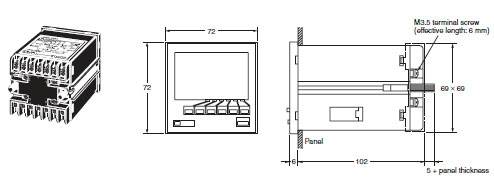
Panel Cutouts
Panel cutouts are as shown below(according to DIN 43700).
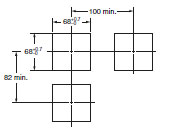
Note: The mounting panel thickness must be 1 to 5 mm.
Features | Counter - H7BX
Degree of protection: IP54 equivalent (front section only) Perform all basic settings with a DIP switch. Total and preset counter, batch counter, dual counter and tachometer
Properties | Counter - H7BX
| Counter | H7CX-R |
|---|---|
| Power supply | 100 – 240 Vac (50 – 60Hz) 24 Vac (50 – 60Hz) 10 – 24 Vdc |
| Max counting speed | 30 Hz |
| Input method | No-voltage (NPN) input / voltage (PNP) input |
| High (logic) level: 4.5 to 30 VDC Low (logic) level: 0 to 2 VDC |
|
| Output | Contact output: 3 A at 250 VAC/30 VDC |
| Reset system | External |
| automatic reset | |
| Output mode | N, F, C, R, K-1, P, Q, A, K-2, D, L, H |
| Dimensions (W x L x H) (mm) |
48 x 48 x 100 |
| Weight (g) | 250 |
Counter - H7BX
ดาวน์โหลดไฟล์ PDF คุณสมบัติ | Counter - H7BX
เครื่องนับจำนวนตามที่ตั้งไว้ล่วงหน้า มีมาตรฐานการป้องกัน IP54 (เฉพาะด้านหน้า), ปุ่มกดทั้งหมดจะเป็นดิฟสวิตซ์ มีรูปแบบการทำงานแบบตั้งไว้ล่วงหน้า, นับแบบเป็นชุด, นับสองอันพร้อมกันและเครื่องวัดความเร็ว
ข้อมูลจำเพาะ | Counter - H7BX
| Counter | H7BX |
|---|---|
| แหล่งจ่ายไฟ | 100–240Vac (50-60 Hz) / 24Vac (50-60Hz) / 10-24Vdc |
| ความเร็วการนับสูงสุด | 30 Hz |
| รูปแบบของอินพุต | แบบ NPN และ PNP |
| 4.5 -30 Vdc จะเป็น High, 0 – 2 Vdc จะเป็น Low | |
| เอาต์พุต | เอาต์พุตแบบหน้าสัมผัส 3A 250Vac / 30Vdc |
| เอาต์พุตแบบทรานซิสเตอร์ 100mA 30Vdc | |
| รีเซต | แบบต่อภายนอก |
| แบบอัตโนมัติ | |
| รูปแบบเอาต์พุต | N, F, C, R, K-1, P, Q, A, K-2, D, L, and H |
| ขนาด | กว้าง 48 mm / ยาว 48 mm / ลึก 100 mm |
| น้ำหนัก | 250 กรัม |


 Your Lift